
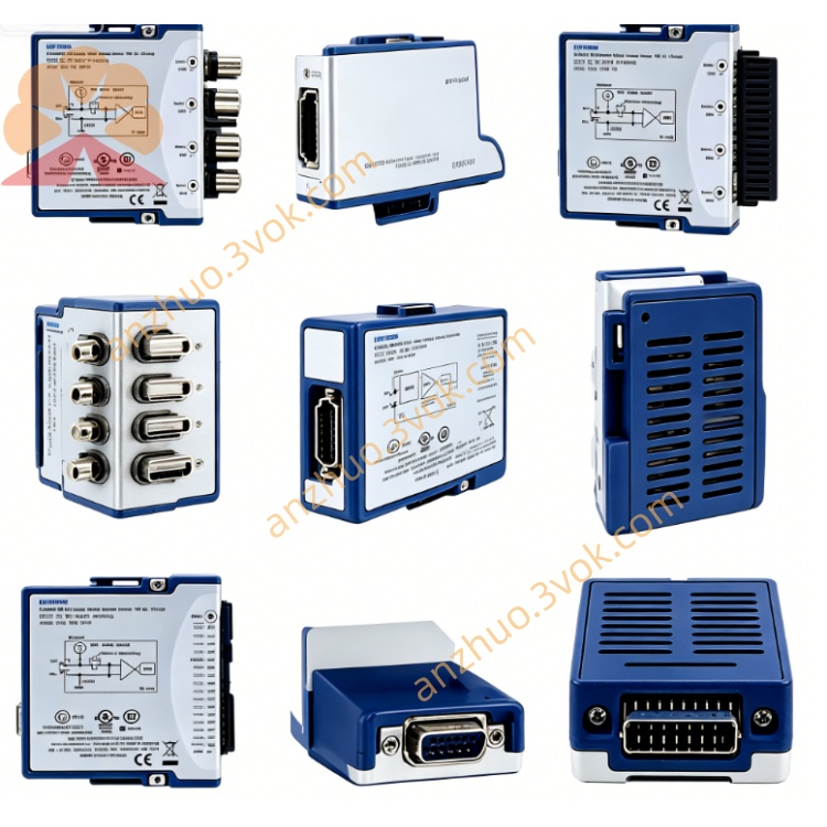
NI PXI‑2530B 128‑Channel Reed‑Relay Multiplexer Switch Module
Description
II. Model Interpretation
PXI: PCI eXtensions for Instrumentation, compatible with standard PXI and PXIe mixed slots.
2530B: NI 2500 series switch module, representing 128 channels, reed relays, multi-topology (multiplexing / matrix), version B specification.
Standard part number: 778572-30.
Product status: Market available.
III. Technical Parameters
1. Channels and Topology Configuration
Relay Type: Reed Relay, fast action, stable contact.
Multiplexing Topology: 128×1 (single wire), 64×1 (double wire), 32×1 (four-wire Kelvin), 8 groups of 16×1 (single wire).
Matrix Topology: 4×32 (single wire), 8×16 (single wire), 4×16 (double wire).
2. Electrical Parameters
Maximum Switching Voltage: 60 VDC / 30 VAC (rms).
Maximum Switching Current: 0.4 A / channel.
Maximum Switching Power: 24 W (DC), 12 VA (AC).
On-Resistance: Typical ≤ 150 mΩ.
Bandwidth: DC to 12 MHz (-3 dB).
Relay Lifespan: Typical 10⁸ actions under resistive load.
3. Dynamic Performance
Typical Switching Time: < 1 ms (pull-in / pull-out).
Maximum Scanning Rate: 900 cycles / second.
Scanning List: Supports 32,000 steps for deterministic scanning.
4. Physical and Environmental Parameters
Form Specification: Standard 3U PXI single-slot module.
Size: 21.6 cm × 2.0 cm × 13.0 cm.
Weight: 266 g.
Operating Temperature: 0 ℃~55 ℃.
Storage Temperature: -40 ℃~70 ℃.
Operating Humidity: 5%~85% RH (no condensation).
Module Power Consumption: 4.2 W at 5V supply, 1.2 W at 3.3V supply.
IV. Interface and Communication Configuration
Bus Interface: Standard PXI mixed bus, supports hot plugging, plug-and-play, compatible with PXI/PXIe chassis.
Signal Interface: Front panel equipped with 160-pin LFH high-density female connector, suitable for various topologies such as single wire, double wire, and four-wire Kelvin connections.
Synchronous Trigger: Integrated PXI universal trigger line (0–7), supports hardware trigger and front panel trigger input/output, enabling multi-module synchronous scanning and timing linkage.
Software Driver: Companion NI-SWITCH driver, compatible with LabVIEW, TestStand, LabWindows/CVI development environments, supports C/C++/Python API and IVI standard driver.
V. Core Functions
Flexible Switching of Multi-topology: Supports both multiplexing and matrix modes, covering single wire, double wire, and four-wire Kelvin measurement requirements, suitable for voltage, current, resistance and other precision measurement scenarios.
High-density Channel Integration: Single module 128 channels, scalable to build large-scale signal routing systems, saving chassis slots and system costs.
High-speed Low-Latency Switching: Reed relays achieve sub-millisecond switching speed, 900 cycles / second scanning rate, enhancing multi-channel testing efficiency.
Low Contact Resistance and High Bandwidth: Typical 150 mΩ on-resistance, 12 MHz bandwidth, suitable for high-frequency and low-level signal transmission.
Deterministic Scanning and Synchronization: Supports long scanning lists and hardware trigger synchronization, ensuring consistency and data stability of multi-channel measurements.
VI. Application Scenarios Semiconductor and electronic testing: High-density functional testing, parameter inspection and signal routing for chips, circuit boards, and components.
Precise data acquisition system: Multi-channel acquisition and calibration of low-voltage / weak signals such as thermocouples, strain gauges, and sensors.
Automated ATE equipment: Batch production testing and aging screening for consumer electronics, communication equipment, and industrial control boards.
Power and load testing: Synchronous detection of voltage / current / resistance for multiple low-voltage power supplies, DC-DC modules, and battery packs.
Laboratory and R&D testing: Signal switching of multiple instruments, construction of multi-channel parallel testing systems, supporting the execution of complex test sequences.
VII. Installation and Maintenance Instructions
Connection and Installation
Modules must be unplugged while the entire machine is powered off. After insertion into the PXI/PXIe standard slot, tighten the fixing screws; connect 160-pin LFH interface cables according to the topology specification, strictly controlling the input voltage and current to not exceed the rated values of 60 V and 0.4 A; ensure reliable grounding of the chassis and the tested equipment to reduce electromagnetic interference and the risk of electric shock; avoid placing the reed relay module close to controllers with mechanical hard drives to prevent magnetic field interference.
Software Operation
After powering on the equipment, install the complete NI-SWITCH driver on the host, complete module identification and channel topology configuration through NI-MAX; write programs based on the corresponding development software to achieve functions such as channel switching, automatic scanning, and synchronous measurement; configure multi-modules for synchronization using the hardware trigger function to improve the timing accuracy of the test system.
Daily Maintenance
After regular power-off, use a dust-free soft cloth to clean the module panel and interfaces to prevent dust and liquids from entering the ports; the operating environment of the equipment should be maintained at 0–55 ℃ without condensation, avoiding strong electromagnetic interference and strong magnetic fields; avoid connecting inductive loads; if connecting inductive components, an surge protection circuit must be added to extend the lifespan of the relay; when plugging or unplugging modules and connecting wires, wear an anti-static wristband to prevent static discharge from damaging the internal circuits.
Get a Quote