
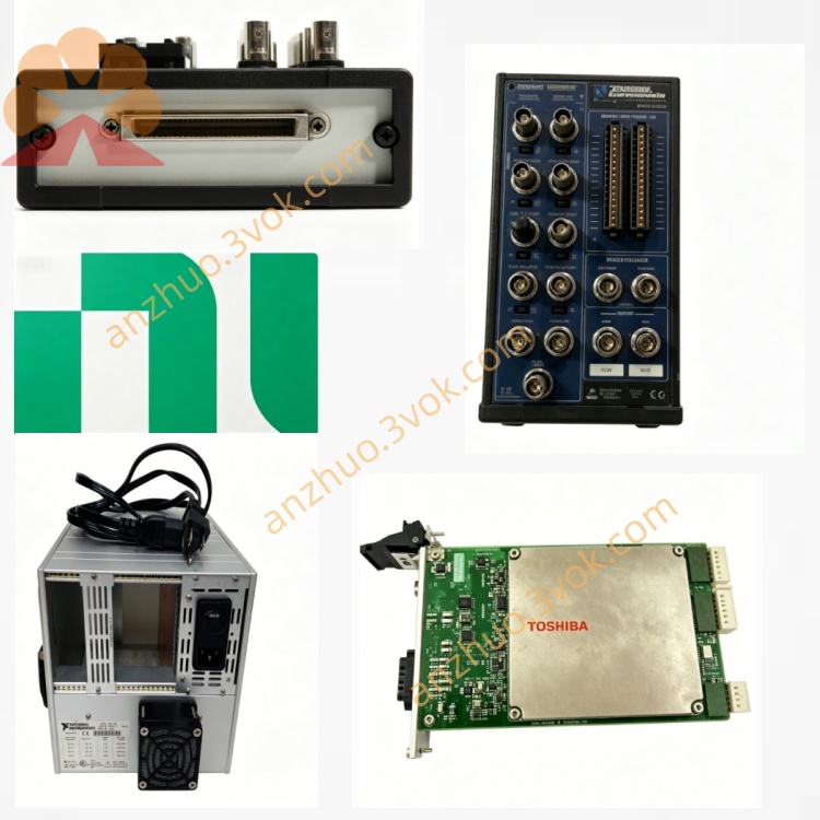
PXI‑2523 26‑Channel 2A DPDT Electromechanical‑Relay Module
Description
II. Model Interpretation
PXI: PCI eXtensions for Instrumentation, compatible with PXI/PXIe hybrid slots.
2523: 2500 series (general-purpose relay switch), 23 represents 26 channels, DPDT double-pole double-throw, 100V/2A specification.
Part Number: 778572-23.
Status: In stock (NI mainstream DPDT general switch module).
III. Technical Parameters
Channel Configuration
Relay Type: 26 independent DPDT (Form C, double-pole double-throw) non-retentive armature relay.
Topology: 26 fully independent double-pole channels, each channel includes COM+/COM− (common terminal), NO+/NO− (normally open), NC+/NC− (normally closed).
Electrical Characteristics
Maximum switching voltage: 100 VDC (channel-to-channel / channel-to-ground, CAT I).
Maximum switching current: 2 A (per channel, switching / carrying).
Maximum switching power: 60 W, 62.5 VA (DC–60 Hz, per channel).
On-resistance: <0.5 Ω (typical).
Thermal offset: Low (suitable for precise differential measurement).
Relay Life: 10^8 times (mechanical life, typical).
Contact Material: Palladium-ruthenium alloy plated gold (low contact resistance, corrosion-resistant).
Dynamic Performance
Bandwidth: 36 MHz.
Switching Time: <1 ms (typical).
Scan Rate: 145 cycles/second.
Physical and Environmental
Size: 3U PXI (100 mm×160 mm), single slot.
Weight: Approximately 0.35 kg.
Operating Temperature: 0–55 °C; Storage: −40–70 °C.
Humidity: 10%–90% RH (no condensation).
Power Consumption: 5 W (5 V).
IV. Interface and Communication Configuration
Host Interface: PXI hybrid bus (compatible with PXIe/PXI), supports hot plugging, plug-and-play.
Signal Interface: 160-pin DIN 41612 female connector (front panel), each channel leads out COM+/COM−, NO+/NO−, NC+/NC−, suitable for differential / floating ground wiring.
Trigger and Synchronization: PXI trigger line (0–7, minimum pulse width of 150 ns), supports multi-module synchronous scanning and timing control.
Driver Software: Compatible with NI-SWITCH, LabVIEW, TestStand, C/C++/Python API, supports IVI standard driver.
V. Core Functions
26 independent DPDT double-pole double-throw switching: Each channel can achieve differential dual-line common terminal and NO/NC dual-select, suitable for differential signals, floating ground load, avoiding common ground interference from NI.
Medium-power differential switching: 100 V/2 A double-pole synchronous switching, covering low-voltage differential power supply, sensors, actuators (heaters, fans, solenoid valves) control requirements.
Low-resistance low-noise precise switching: <0.5 Ω on-resistance + low thermal offset, suitable for precise differential voltage / current signal routing and measurement.
Built-in relay count: Built-in action count, supports predictive maintenance, early replacement of aged relays.
Software programmable and scanning: Supports immediate control and list scanning, suitable for automated test sequences and real-time control.
VI. Application Scenarios
Automation Testing (ATE): Differential power / signal routing of circuit boards, modules, systems, functional testing and aging testing.
Differential / Grounded Signal Switching: Dual-line signal switching of sensors, instruments, communication equipment, eliminating common ground interference. Power and Load Control: Low-voltage differential power distribution, relay/contactor drive, heater/fan/valve control.
Industrial Control and Monitoring: Equipment status monitoring, alarm circuit control, small actuator drive.
Automotive Electronic Testing: Differential power / I/O interface testing for on-board ECU, sensors, actuators.
VII. Installation and Maintenance Instructions
Installation and Wiring
Module: Unplug and power off, insert into PXI/PXIe mixed slot, tighten the fixing screws.
Wiring: Connect COM/NO/NC differential loads / tested equipment according to channel definitions. Do not exceed 100 V, 2 A.
Grounding: Secure the chassis to the system ground to reduce electromagnetic interference.
Software Configuration
Install NI-SWITCH driver, NI-MAX recognizes the module, configure DPDT channel topology.
Programming: Call the switch VI in LabVIEW, or configure the test sequence in TestStand to achieve channel control and scanning.
Daily Maintenance
Cleaning: Wipe the panel with a soft cloth after power off, avoid liquid entering the DIN interface.
Environment: Operating temperature 0–55 °C, avoid dust, moisture, strong electromagnetic interference.
Protection Mechanism: Avoid overvoltage (>100 V), overcurrent (>2 A), inductive loads (without surge suppression), extend relay lifespan.
Static Protection: Wear an anti-static wristband when plugging and unplugging the module, ensure good grounding of the chassis.
Get a Quote