
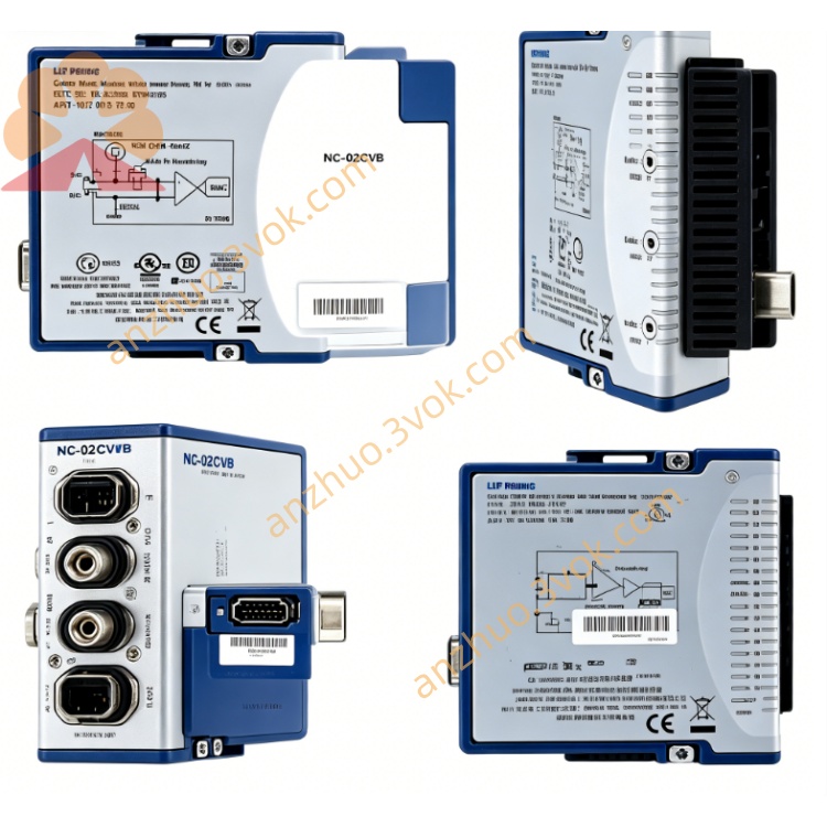
NI PXI‑2510 68‑Channel 2‑A Fault Insertion Switch Module
Description
II. Model Interpretation
PXI: PCI eXtensions for Instrumentation, compatible with PXI/PXIe hybrid slots.
2510: 2500 series (signal insertion / fault switch), 10 represents 68 channels, high voltage / current, dual fault bus type.
Part Number: 778572-10 (standard model).
Status: In stock (NI's mainstream HIL test dedicated module).
III. Technical Parameters
Channel Configuration:
Balanced Input Channels: 68 channels (each channel can be independently open-circuited / short-circuited)
Fault Bus: 2 channels (configurable as ground, battery, power supply, etc.)
Topology: Each channel supports four states: "Break", "Short-circuit to Bus 1/2", "Direct Connection"
Electrical Characteristics:
Maximum Switching Voltage: 150 VDC
Maximum Switching / Carrying Current: 2 A (per channel)
Maximum Switching Power: 60 W (per channel)
Relay Type: Electromechanical, thermal offset < 1 μV
Conduction Resistance: < 1.5 Ω (typical)
Dynamic Performance:
Bandwidth: 6.5 MHz
Scanning Rate: Up to 100 channels per second
Relay Life: ≥ 10^6 times (rated load)
Physical and Environmental:
Size: 3U PXI (100 mm × 160 mm)
Weight: Approximately 0.3 kg
Operating Temperature: 0–55 °C; Storage: −40–70 °C
Humidity: 10%–90% RH (no condensation)
IV. Interface and Communication Configuration
Host Interface: PXI hybrid bus (compatible with PXIe/PXI slots), supports hot plugging, plug-and-play.
Signal Interface: 160-pin DIN 41612 female connector (front panel), equipped with dedicated terminal blocks / cables for connecting DUT and fault bus.
Trigger and Synchronization:
PXI Trigger Line: 70 ns resolution, supports multi-module synchronization
Hardware Trigger: Front panel trigger input / output, compatible with HIL real-time timing
Driver Software: Compatible with NI-SWITCH, LabVIEW Real-Time, NI VeriStand, TestStand, C/C++/Python API.
V. Core Functions
Multiple Types of Fault Simulation: 68-channel independent control, simulating open circuit, ground short circuit, power short circuit, pin-to-pin short circuit, covering the mainstream scenarios of electrical faults.
High Power and High Voltage Switching: 150 VDC/2 A/60 W capability, suitable for automotive 12/24 V, aerospace 28 V and other power-level signal fault injection.
Dual Fault Bus Flexible Configuration: 2 programmable fault buses, can be mapped to ground, battery positive/negative, reference voltage, achieving complex fault combinations.
HIL Real-time Integration: Combined with LabVIEW Real-Time/VeriStand, supports microsecond-level timing control, suitable for ECU/FADEC and other real-time system testing.
High-density Channel Expansion: Single module 68 channels, cascading multiple modules can be expanded to hundreds of channels, meeting the requirements of vehicle / system-level fault injection.
VI. Application Scenarios
Automotive Electronic HIL Testing: Engine ECU, body controller, BMS, ADAS system fault injection and robustness verification.
Aerospace Testing: FADEC, flight control system, aerospace electronic equipment short-circuit / open-circuit fault simulation and reliability testing.
Industrial Control and Embedded Systems: PLC, motion controller, industrial gateway's electrical fault fault-tolerant capability verification. Electronic reliability testing: Durability and failure mode analysis of PCB, wiring harness, and connectors.
Power and load testing: Verification of overvoltage / short circuit / open circuit fault protection mechanisms for power modules and battery management systems.
VII. Installation and Maintenance Instructions
Installation and Wiring:
Module: Unplug and disconnect during power off, insert into PXI/PXIe mixed slot, tighten the fixing screws.
Wiring: Connect the 160-pin interface to the DUT (test equipment) and the fault bus according to channel definitions, avoid overvoltage / overcurrent wiring.
Grounding: Reliable connection of the chassis to the system ground, independent grounding of the fault bus to reduce interference.
Software Configuration:
Install NI-SWITCH and VeriStand drivers, NI-MAX recognizes the module, configure the fault bus mapping.
Programming: Call the switch VI in LabVIEW Real-Time, or configure the real-time fault sequence through VeriStand.
Daily Maintenance:
Cleaning: Wipe the panel with a soft cloth after power off, avoid liquid entering the 160-pin interface.
Environment: Working temperature 0–55 °C, avoid dust, moisture, and strong electromagnetic interference.
Relay Life: Avoid overvoltage (>150 V), overcurrent (>2 A), and regularly check the contact status.
Static Protection: Wear an anti-static wristband when plugging and unplugging the module, ensure good grounding of the chassis.
Get a Quote