
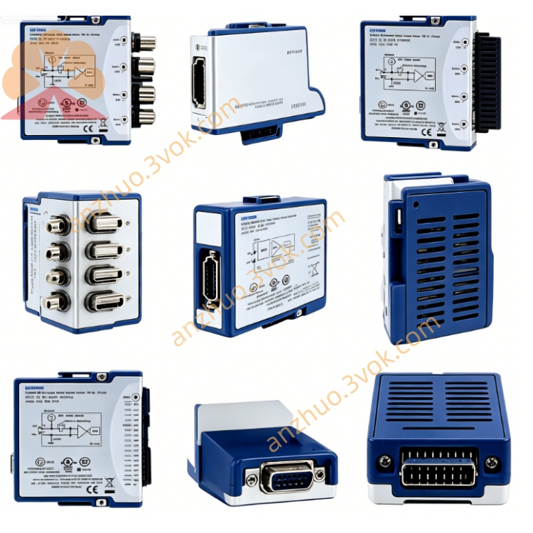
NI PXI‑2501 24‑Channel FET Multiplexer Matrix Switch Module
Description
II. Model Interpretation
PXI: PCI eXtensions for Instrumentation, a PCI expansion bus standard for instruments.
2501: 2500 series (PXI switch module), 01 represents 48 channels, FET, 1/2/4 lines, low voltage type.
Part Number: 778572-01 (standard model).
Status: Out of production (NI no longer sells, second-hand / inventory available for purchase).
III. Technical Parameters
Channel Configuration:
1 line: 48×1 multiplexer
2 lines: 24×1, dual 12×1, four 6×1 multiplexers
4 lines: 12×1 multiplexer
Matrix: 2 lines 4×6 matrix NI
Electrical Characteristics:
Maximum operating voltage: ±10 VDC (grounded)
Overvoltage protection: ±25 VDC (power-on), ±15 VDC (power-off)
FET conduction resistance: 50 Ω (typical), 85 Ω (maximum, 25 °C)
Signal Path Resistance: 1,650 Ω (typical)
Dynamic Performance:
Setup Time: 30 μs (to 0.01% accuracy)
Scanning Rate: Up to 15,000 channels per second
Scanning List: 1,024 steps (deterministic scanning)
Physical and Environmental:
Size: 3U PXI (100 mm×160 mm)
Weight: Approximately 0.45 kg
Operating Temperature: 0–55 °C; Storage: −40–70 °C
Humidity: 10%–90% RH (no condensation)
IV. Interface and Communication Configuration
Host Interface: Standard PXI backplane (32-bit PCI), supports plug-and-play, hot swapping.
Signal Interface: 68-pin SCSI female connector (front panel), equipped with terminal block (e.g., TB-2501) for 1/2/4 line switching.
Trigger and Synchronization:
PXI Trigger Line: 70 ns resolution, supports input/output triggering
Front Panel Trigger: 500 ns resolution, pulse width 1 μs
Scanning Trigger: Software/hardware triggering, synchronizes multi-module scanning
Driver Software: Compatible with NI- SWITCH, LabVIEW, LabWindows/CVI, C#/Python API.
V. Core Functions
Flexible Topology Configuration: 48 channels support 1/2/4 line multiplexing and 4×6 matrix, suitable for voltage, current, resistance, thermocouple, etc. signals.
High-Speed Non-Mechanical Switching: FET switch has no mechanical wear, 30 μs setup time, 15,000 channels per second, suitable for high-speed continuous testing.
Low Voltage High Precision: ±10 V range, low conduction resistance, overvoltage protection, ensures weak signal integrity and system safety.
Deterministic Scanning: 1,024-step scanning list, programmable timing, synchronizes multi-modules, suitable for complex timing tests.
High-Density Channel Expansion: Single module 48 channels, expands DAQ/instrument channels, reduces system cost and size.
VI. Application Scenarios
Low Voltage Signal Acquisition: Sensors (strain / pressure / temperature), thermocouples, RTD, multi-channel scanning of weak voltage signals.
Automated Test System: Electronic product functional testing, multi-station parallel testing, parameterized testing (voltage / resistance / current).
Data Acquisition Channel Expansion: Expansion of PXI DAQ module channels to achieve high-channel number synchronous acquisition.
Research and Laboratory: Precision measurement, material testing, biological signal acquisition, multi-channel monitoring.
Semiconductor Testing: Wafer testing, chip parameter testing, low-voltage signal routing. VII. Installation and Maintenance Instructions
Installation and Wiring:
Module: Unplug and power off for insertion, insert into the 3U slot of the PXI chassis, and tighten the fixing screws.
Terminal Block: Use TB-2501, connect according to the topology (1/2/4 wires), avoid short circuits.
Grounding: Secure the signal ground and chassis ground connection to reduce noise.
Software Configuration:
Install NI-SWITCH driver, NI-MAX recognizes the module, configure topology and scan list.
Programming: Directly call the switch VI in LabVIEW, or control channel switching and scanning using C#/Python.
Daily Maintenance:
Cleaning: After power off, wipe the panel with a soft cloth to avoid liquid entering the interface.
Environment: Operating temperature 0–55 °C, avoid dust, moisture, and strong electromagnetic interference.
Life: FET has no contacts, long lifespan; avoid overvoltage (>±10 V), static electricity shock.
Static Protection: Wear an anti-static wristband when plugging and unplugging the module to ensure good chassis grounding.
Get a Quote