A16B-1100-0070/02A
Description
1. General Information
Model: A16B-1100-0070/02A
Manufacturer: FANUC
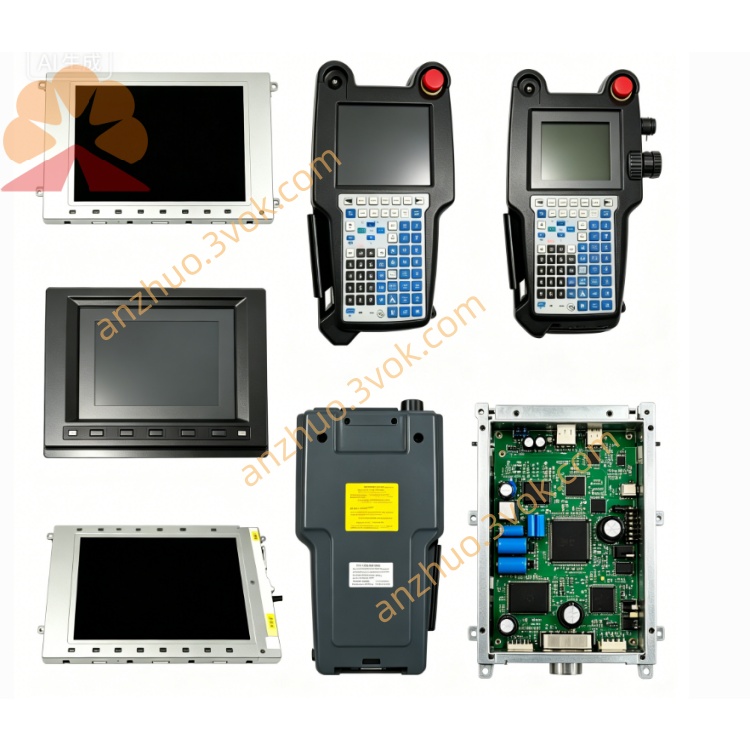
Type: Digital Spindle Control Board (PCB)
Series: S‑series AC spindle drive (older generation)
Application: CNC machine tools, spindle motor control (1S–3S series)
Revision: /02A (hardware version)
2. Specifications
Function: Digital control, speed/position loop, I/O interface, protection logic
Signal Processing: Closed‑loop vector control, serial encoder feedback
Power Supply: +5 V, ±15 V (from drive power unit)
Control Signals: Spindle enable, direction, speed command, alarm output
Feedback Interface: Serial spindle encoder (α or β type)
Protection: Overcurrent, overvoltage, overheat, speed deviation, encoder fault
3. Mechanical & Environmental
Dimensions (H×W×D): Approx 230 × 160 × 30 mm
Weight: Approx 1.5 kg
Mounting: Vertical installation in spindle drive unit
Operating Temp: 0 °C to +55 °C
Storage Temp: −30 °C to +85 °C
Humidity: 10%–90% RH, non‑condensing
Cooling: Natural convection (drive internal airflow)
4. Compatibility
Spindle Drives: FANUC S‑series AC spindle servo units (medium/large size)
Spindle Motors: 1S, 2S, 3S series AC spindle motors
CNC Systems: Compatible with FANUC 0‑series, 16/18/21‑series (legacy)
5. Common Alarms & Troubleshooting
SP‑01: Spindle overcurrent → Check motor insulation, wiring, or power module
SP‑02: Overvoltage → Check input voltage, regeneration circuit
SP‑03: Undervoltage → Check power supply, fuses, wiring
SP‑04: Overheat → Check cooling fan, heat sink, ambient temp
SP‑05: Speed deviation → Check encoder, wiring, motor load
SP‑06: Encoder communication error → Check encoder cable, connector
6. Maintenance
Visual Inspection: Check for burnt components, swollen capacitors, loose connectors
Cleaning: Remove dust from PCB surface and connectors every 3–6 months
Connector Check: Ensure all pins are secure and free of oxidation
Voltage Check: Verify +5 V and ±15 V supply voltages
Encoder Test: Check encoder signal quality and wiring integrity
7. Safety Notes
High Voltage: Ensure drive is fully powered off and capacitors discharged before service
ESD Protection: Use anti‑static wristband when handling PCB
Qualified Personnel: Only trained technicians should perform maintenance
Genuine Parts: Use only FANUC original replacement parts
Get a Quote