A06B-6114-H211
Description
1. General Information
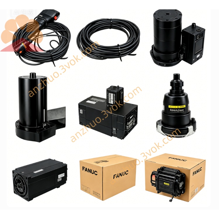
Model: A06B-6114-H211 (SVM2‑160/160i, αiSV‑160/160)
Type: Dual‑axis integrated AC servo amplifier (Alpha i series)
Manufacturer: FANUC
Description: Compact, high‑performance 2‑axis drive for CNC machine tools, machining centers, lathes, and multi‑axis automation equipment.
Applicable Motors: FANUC αi / βi series servo motors
Manual Reference: B‑65282EN (FANUC αi Servo Amplifier Series)
2. Electrical Specifications
Input Voltage: 3‑phase AC 200–240 V ±10%, 50/60 Hz
DC Link Voltage: 283–339 V
Rated Input Power: 13 kW
Output Voltage: 0–240 V AC, 3‑phase
Continuous Output Current (RMS):
Axis L: 39 A
Axis M: 39 A
Peak Output Current: 2× continuous (max 0.5 s)
Current Limit (L/M): 160 A (nominal)
Control Method: Full digital vector control (HRV3)
Feedback Interface: Incremental encoder / serial absolute encoder
Communication: FSSB (FANUC Serial Servo Bus), 12 Mbps; COP10A/B optical connectors
Cooling: Forced air cooling (internal + external fan)
Insulation Class: Class H (180 °C)
3. Environmental & Mechanical
Operating Temperature: 0 °C to +55 °C
Storage Temperature: −20 °C to +70 °C
Humidity: 5–95% RH, non‑condensing
Altitude: ≤1000 m (derate 1% per 100 m above 1000 m)
Vibration: ≤0.5 G (4.9 m/s²)
Protection Class: IP20 (front face)
Mounting: Vertical installation in control cabinet
Dimensions (W×H×D): 90 mm × 200 mm × 300 mm
Weight: Approx. 6.8 kg (15.0 lbs)
4. Key Features
Dual‑axis integration: Saves cabinet space and reduces wiring
High‑speed response: HRV3 control, 1 μs cycle time
High positioning accuracy: Supports 1 μm level precision
Dual encoder support: Incremental / absolute serial encoder
Hot‑swap fan design: Internal fan replaceable without full disassembly
Built‑in protection: Overcurrent, overvoltage, undervoltage, overtemperature, overload, encoder failure, fan fault
LED status indicators: Power, alarm, FSSB communication
Advanced diagnostics: Real‑time monitoring for maintenance
5. Installation Instructions
Power off: Disconnect all power before installation or wiring.
Mounting: Install vertically on a rigid cabinet rail; maintain ≥50 mm clearance top and bottom for airflow.
Input wiring: Connect 3‑phase AC power (L1/L2/L3) and protective earth (PE).
Motor wiring: Connect motor power cables to U/V/W terminals for L/M axes.
Feedback wiring: Connect encoder cables to respective feedback connectors.
Communication wiring: Connect FSSB/COP10 optical cable to CNC controller.
Terminal torque: Tighten all terminals to 1.2–1.5 N·m.
Fan check: Verify internal/external fans operate normally after power‑on.
6. Maintenance & Troubleshooting
Routine Maintenance
Clean air filter every 1–3 months.
Check internal/external fan operation monthly; replace if noisy or stopped (Internal fan: A90L‑0001‑0510; External fan: A90L‑0001‑0508).
Inspect terminals and cables for tightness or damage every 6 months.
Common Alarms
ALM 1 (FAL): Internal fan stopped.
ALM 2 (LV5V): Low control power voltage.
ALM 5 (LVDC): Low DC link voltage.
ALM 6/b: Inverter overheat.
ALM 8 (HCL): L‑axis overcurrent.
ALM 9 (HCM): M‑axis overcurrent.
ALM F: External cooling fan stop.
ALM P: Communication error (check FSSB/COP10 cable).
7. Safety Precautions
Installation and servicing must be performed by qualified electricians.
High voltage remains for ≥10 minutes after power‑off; wait before touching terminals.
Do not block ventilation openings—risk of overheating and fire.
Use only FANUC‑specified cables and connectors to ensure safety and compatibility.
Ground the amplifier housing properly to avoid electric shock.
Get a Quote