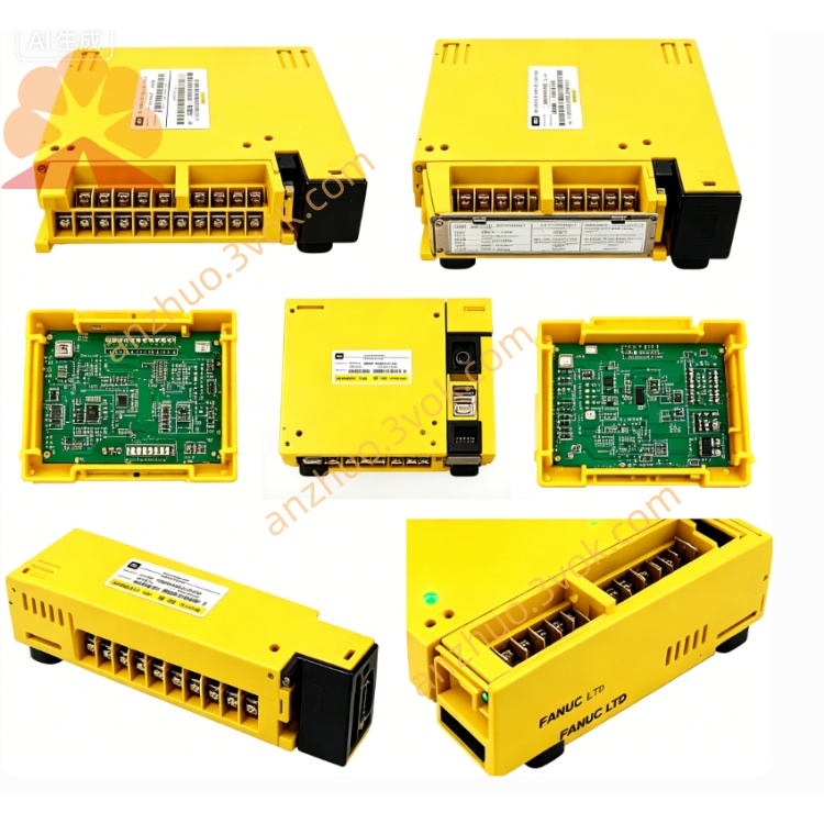
AIF01A
Description
1. General Information
Model: AIF01A
FANUC Part Numbers:
A03B-0807-C011 (for 16i/18i/21i‑A series)
A03B-0819-C011 (for 16i/18i/21i‑B series)
Type: FSSB (FANUC Servo Bus) I/O Interface Module
Function: Acts as a bus bridge between the CNC system and ABU05A/ABU10A I/O racks, managing all I/O module communications.
Weight: Approx. 0.2 kg (0.44 lbs)
Installation: Must be inserted into the leftmost slot of the ABU05A (5‑slot) or ABU10A (10‑slot) I/O rack.
2. Specifications
Communication Protocol: FSSB (high‑speed servo bus)
Controllable I/O Modules:
ABU10A: Up to 10 modules
ABU05A: Up to 5 modules
Power Supply: 24 VDC ±10%, max. 2 A
Power Consumption: ≤ 10 W
Interfaces:
JD1B: FSSB input (from CNC or upstream module)
JD1A: FSSB output (to downstream I/O module)
CP1: 24 VDC power input
Operating Temperature: −10°C to +50°C
Storage Temperature: −20°C to +70°C
Protection Class: IP20 (front panel)
Dimensions (W×H×D): 100 mm × 50 mm × 30 mm
3. Compatibility
3.1 CNC Systems
✅ 16i‑A / 18i‑A / 21i‑A (uses A03B-0807-C011)
✅ 16i‑B / 18i‑B / 21i‑B (uses A03B-0819-C011)
✅ 0i‑B / 0i‑C (when paired with ABU racks)
3.2 I/O Racks
✅ ABU05A (5‑slot base unit)
✅ ABU10A (10‑slot base unit)
4. Main Features
Real‑time Communication: High‑speed data transmission for all digital/analog I/O modules in the rack.
Bus Stability: Robust FSSB bus design with strong anti‑interference capability.
Easy Installation: Standard rack‑mounting structure for quick replacement.
LED Status Indicators: For power, run, and fault diagnostics.
Centralized Management: Controls digital inputs/outputs, analog modules, and special function modules.
5. Installation Procedure
Power Off: Cut off all power to the CNC and I/O rack.
Insert Module: Slide the AIF01A into the leftmost slot of the ABU05A/ABU10A rack.
Secure: Tighten the front‑panel fixing screws.
Connect Power: Attach the 24 VDC power cable to the CP1 terminal.
FSSB Cabling:
Connect the CNC’s FSSB port to JD1B (input).
Daisy‑chain to subsequent I/O modules via JD1A (output).
Power On: Restore power and verify LED indicators for normal operation.
6. Maintenance & Troubleshooting
6.1 Routine Maintenance
Check cable connections and screw tightness periodically.
Keep the module surface clean and free of dust/oil.
Do not disassemble the module without authorization.
6.2 Common Issues
No Bus Communication:
Check 24 VDC power supply.
Inspect FSSB cable integrity and connections at JD1A/JD1B.
System I/O Alarms:
Re‑seat the AIF01A module.
Check for damage to the FSSB bus line.
LED Fault Indicator:
Verify CNC system configuration for FSSB axis assignment.
Check for short circuits in the I/O rack modules.
7. Ordering Information
Model: AIF01A
Description: FSSB I/O Interface Module for FANUC ABU I/O Racks
Part Numbers:
A03B-0807-C011 (for A‑series CNC)
A03B-0819-C011 (for B‑series CNC)
Get a Quote