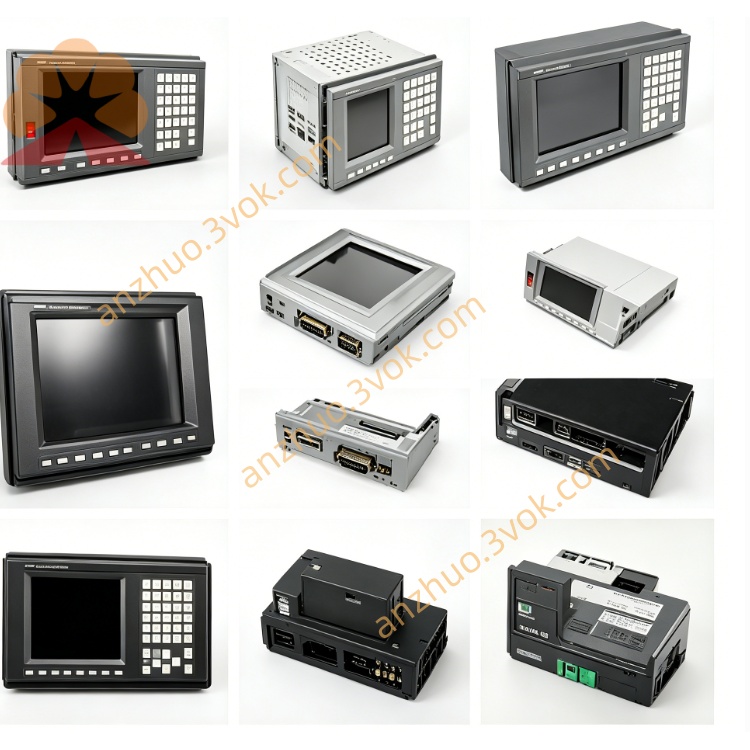
A20B-2100-0541
Description
Specifications
Power Supply: DC 5V ±5%, DC 24V ±10%
Control Axes: 2‑axis simultaneous control (SVM2‑80/80)
Communication: FSSB (FANUC Serial Servo Bus) optical interface
Feedback: α/αi encoder compatible (A/B/Z phase, serial)
Operating Temperature: 0°C to +40°C (non‑condensing)
Storage Temperature: -20°C to +60°C
Humidity: ≤95% RH, no condensation
Protection: Overvoltage, overcurrent, short‑circuit, thermal, encoder fault; Daito LM32 fuse onboard
Indicators: LCD for status/alarm numbers; LED status indicators
Cooling: Passive cooling
Compatibility
Servo Amplifiers: A06B‑6096‑H201/H202 (α SVM2 2‑axis)
CNC Systems: FANUC 0i‑MF/TF, 30i/31i/32i‑B, 16i/18i/21i‑B series
Servo Motors: FANUC αi‑B, αi‑F, αBi series AC servo motors
Replaces: A20B-2100-0540 / 0542 (pin‑to‑pin compatible)
Common Alarms & Troubleshooting
Alarm 400/401 (Servo Not Ready): Check 24V supply, FSSB optical cable, or LM32 fuse.
Alarm 410/411 (Servo Error): Verify encoder wiring, 5V supply, or PCB track damage.
FSSB Communication Fail: Reseat optical connector; clean dirt on fiber ends.
Overheat Alarm (430/431): Clean drive fans; clear blocked ventilation slots.
No LCD/LED: Confirm 5V power input and board seating in drive slot.
Installation & ESD Precautions
Power OFF the drive and wait ≥5 minutes for capacitor discharge.
Use anti‑static wrist strap and ESD‑safe mat.
Align board with drive slot, insert firmly, and secure mounting screws.
Reconnect FSSB optical cable, encoder cables, 24V power, and battery connectors.
Power on; check LCD for normal status and test servo homing/positioning.
Maintenance
Clean dust from PCB and connectors quarterly (use dry air blower).
Inspect FSSB optical connectors for cleanliness and tightness.
Check LM32 fuse and components for overheating signs (discoloration, bulging).
Keep drive enclosure dry and free of oil mist.
Get a Quote