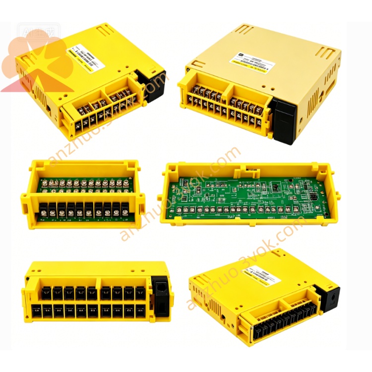
A20B-2000-0170
Description
Specifications
Electrical
Input Voltage: DC 24 V ±10%
Power Consumption: ≤ 2.5 A
System Bus: 32‑bit
Axis Support: Up to 4 axes (standard); expandable to 6
Servo Interface: Analog / digital / serial servo compatible
Environmental
Operating Temp: 0°C ~ 45°C
Storage Temp: -20°C ~ +70°C
Humidity: 5%–85% RH (non‑condensing)
Altitude: ≤1000 m
Protection: IP20 (indoor cabinet)
LED Status Indicators (onboard)
L1 (Green): Blinking = normal operation
L2 (Red): ON = system alarm (check CRT alarm code)
L3 (Red): ON = no memory card detected
L4 (Red): ON = watchdog / servo / axis card alarm (Alarm 920)
L5 (Red): ON = sub‑CPU watchdog / 5th/6th servo alarm
L6 (Red): ON = analog interface / DNC1 card fault
Safety Precautions
Power Off & Discharge: Disconnect 24 VDC and main AC; wait ≥5 minutes for capacitors to discharge.
ESD Protection: Always wear anti‑static gloves/wrist strap when handling the PCB.
No Live Work: Never insert/remove boards or cables with power applied.
Critical Component: Faulty installation may cause machine crash or injury.
No Modification: Unauthorized circuit changes void warranty and may cause fire/shock.
Installation Steps
Lockout/Tagout: Cut off all power; secure to prevent re‑energization.
ESD Setup: Use anti‑static gear.
Slot Insertion: Align PCB with backplane slot; insert firmly.
Secure Board: Tighten mounting screws (0.6–0.8 N·m).
Sub‑board Connection: Install MEM (memory), AXS (axis), I/O boards as required.
Cable Connection: Connect power, CRT/MDI, servo, spindle, and I/O cables per diagram.
Power‑on Test: Restore power; check LED L1 blinks and no red LEDs stay ON.
Compatibility
CNC Systems: 0‑MC, 0‑TC, 0‑MD, 0‑TD
Servo Drives: Analog (e.g., A06B‑604x), digital, serial types
Sub‑boards:
MEM: A20B‑2000‑016x series
AXS: A20B‑2000‑018x series
I/O: A20B‑2000‑019x series
Maintenance
Quarterly Inspection: Check for burnt components, swollen capacitors, or discoloration.
Connector Check: Every 3 months, reseat and inspect all edge connectors for corrosion.
Cleaning: Use dry soft cloth only; no liquid cleaners.
Backup: Monthly save system parameters and PMC programs.
Troubleshooting
- System No Power / Black Screen
Check 24 VDC input and fuse.
Reseat master board and power connectors.
Verify backplane voltage distribution.
- Alarm 920 (Watchdog)
Reseat memory card and sub‑boards.
Check for short circuits or component damage.
Replace master board if alarm persists.
- Servo Alarm / Axis Not Moving
Check AXS board seating and servo cables.
Verify servo amplifier power and enable signals.
Inspect encoder wiring and feedback.
- L3 ON (No Memory Card)
Reseat or replace memory card.
Check card slot contacts for dirt/bending.
Get a Quote