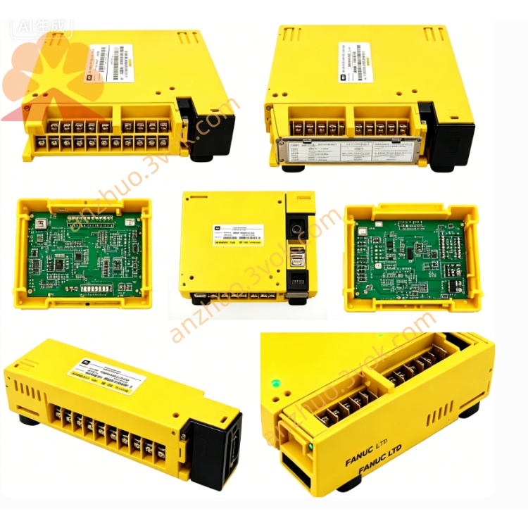
A20B-1008-0740
Description
Technical Specifications
Electrical
Input Voltage: DC 24 V ±10%
Current Consumption: ≤150 mA
E‑Stop Input: 2‑channel redundant (NC/NO selectable)
Safety Output: 2‑channel relay (rated 250 VAC / 3 A)
Response Time: ≤20 ms (from trigger to output cut‑off)
Environmental
Operating Temp: 0°C ~ 45°C
Storage Temp: -20°C ~ +70°C
Humidity: 5%–85% RH (non‑condensing)
Altitude: ≤1000 m
Protection: IP20 (for indoor cabinet use)
Safety Precautions
Power Off First: Disconnect all power (24 VDC & main AC) before handling; wait ≥3 minutes for discharge.
High Safety Risk: This board is a safety‑critical component; faulty installation may cause death/injury.
ESD Protection: Always use anti‑static gloves/wrist strap when touching the PCB.
No Live Wiring: Never connect/disconnect cables with power applied.
No Modification: Do not alter circuits or components; unauthorized changes void warranty and disable safety functions.
Installation Steps
Power Down & Lockout: Cut off 24 VDC and main power; lockout/tagout to prevent accidental re‑energization.
ESD Setup: Wear anti‑static gear.
Mounting: Insert PCB into standard slot in R‑J3IC/R‑30iA cabinet; tighten screws (0.5–0.8 N·m).
Wiring:
CN1: 24 VDC power (pin1=+24V, pin2=0V)
CN2: E‑stop input (dual channel, per robot wiring diagram)
CN3: Safety relay output (to servo drive/controller interlock)
Check & Power On: Verify all connectors are seated; restore power and test E‑stop function.
Compatibility
Robot Controllers: R‑J3IC, R‑30iA series
Robot Models: Arc Mate 120iB/120iC, M‑16iB, M‑20iA, etc. (matching R‑J3IC/R‑30iA)
Safety Standard: Complies with ISO 10218‑1/2, ANSI/RIA R15.06
Maintenance
Visual Inspection: Quarterly check for burnt components, loose connectors, or discoloration.
Function Test: Monthly test E‑stop response (trigger E‑stop; confirm all axes stop immediately).
Cleaning: Use dry, soft cloth only; no liquid cleaners.
Connector Check: Every 6 months, inspect CN1/CN2/CN3 for corrosion or looseness.
Troubleshooting
E‑Stop Not Responding:
Check 24 VDC input (CN1 pins 1–2).
Verify E‑stop switch wiring (CN2 dual channel).
Reseat PCB and connectors.
False E‑Stop Trigger:
Check for loose signal cables or ground loops.
Inspect E‑stop switch for contact wear.
Safety Relay No Output:
Check relay contacts (CN3) for damage.
Verify PCB power and input signals.
Get a Quote