A20B-0008-0371/02
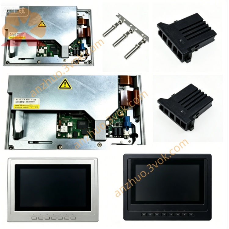
Description
Technical Specifications
Electrical
Input Voltage: 3-phase AC 200–240 V
Rated Power: 2.0 kW
Output Current: Max 10 A
Frequency Range: 0–400 Hz
Overload Capacity: 150% rated output for 60 seconds
Environmental
Operating Temp: 0°C ~ 40°C
Storage Temp: -20°C ~ +80°C
Humidity: 5%–95% RH (non-condensing)
Altitude: ≤1000 m
Protection: IP20
Safety Precautions
Power Off Mandatory: Disconnect all power before installation, removal or maintenance; wait ≥5 minutes for capacitor discharge.
High Voltage Risk: Internal high-voltage components; risk of electric shock. Do not touch exposed circuits.
ESD Protection: Wear anti-static gloves/wrist strap when handling the PCB to avoid static damage.
No Live Operation: Do not operate with covers removed or cables damaged.
No Modification: Unauthorized circuit modification voids warranty and may cause fire/shock.
Installation Steps
Power Off & Discharge: Cut off input power, wait 5+ minutes for residual electricity discharge.
ESD Setup: Wear anti-static gear to protect the board.
Slot Alignment: Align PCB with drive cabinet slot, insert firmly.
Secure Board: Tighten fixing screws to ensure stable installation.
Cable Connection: Connect power, signal and spindle motor cables per wiring diagram; ensure connectors are tight.
Inspection & Power On: Double-check connections; restore power and perform test run.
Maintenance
Regular Cleaning: Use dry soft cloth to remove dust; avoid liquid cleaners.
Connector Inspection: Check connectors every 3 months for looseness/corrosion.
Visual Check: Inspect for burnt components, swollen capacitors or discoloration.
Alarm Handling: Power off, replug connectors and restart if alarms occur; check wiring if problem persists.
Compatibility
Matched Drives: FANUC DC spindle drives (e.g., 6042 series)
CNC Systems: 0i, 16i, 18i, 21i series
Common Troubleshooting
Spindle Not Rotating:
Check PCB seating and connector tightness.
Verify power supply voltage and phase sequence.
Confirm spindle motor wiring correctness.
Speed Fluctuation:
Check for loose signal cables.
Inspect PCB for component aging (e.g., capacitors).
Overload Alarm:
Reduce mechanical load.
Check for motor short circuit or bearing damage.
Get a Quote