A06B-6131-H001
Description
General Description
Part Information
Electrical Specifications
Mechanical & Environmental
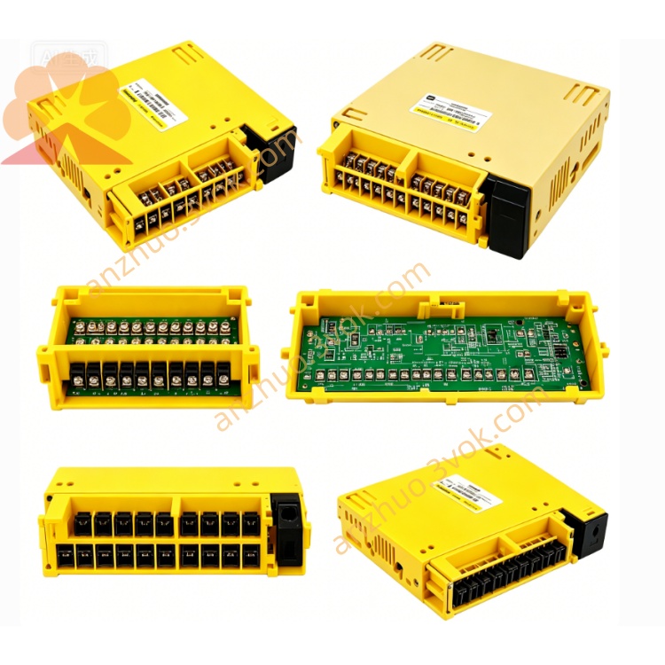
Interface Connectors
COP10A/B: FSSB optical fiber port (to CNC)
CX30: Encoder signal (6‑pin, A06B‑6130‑K204)
CXA19A/B: DC 24V power and control signals
CZ7: Main power input (3‑phase 400–480V)
JX5: Motor power output (U/V/W/PE)
CX29: Emergency stop (E‑STOP) input
Compatible Motors
Features
High‑voltage (400V) design for reduced current and smaller wiring
FSSB optical fiber communication for high‑speed, noise‑immune control
HRV (High Response Vector) control for fast response and smooth motion
Compact, lightweight modular design for easy integration
Built‑in LED indicators (PRDY, ALM, FSSB status) for quick diagnostics
Advanced protection functions ensure system reliability
Installation & Wiring
Mount vertically on a rigid panel with adequate ventilation.
Connect 3‑phase 400–480V AC to CZ7, ensuring correct phase sequence.
Connect DC 24V ±10% to CXA19A/B for control power.
Connect motor U/V/W/PE to JX5; use shielded cables.
Connect encoder cable to CX30; use FANUC‑specified cable.
Connect FSSB optical fiber between COP10A/B and CNC.
Wire E‑STOP signal to CX29; ensure safety circuit compliance.
Tighten all terminals to specified torque; verify insulation and grounding.
Safety Precautions
Disconnect all power before wiring or maintenance; high voltage remains inside after power‑off.
Use only insulated copper wires rated for 600V or higher.
Separate power and signal cables to avoid electromagnetic interference.
Ensure proper protective grounding (PE) to prevent electric shock.
Do not operate with damaged cables or connectors; replace immediately.
Keep within ambient temperature and humidity limits to avoid overheating.
Related Parts
A06B-6130-K204: 6‑pin encoder connector (CX30)
A06B-6130-K203: 3‑pin control signal connector (CXA19)
A06B-6130-K200/K201: Motor power connectors (JX5)
A06B-6130-K202: Discharge resistor connector
FANUC βiS‑xxHV: Compatible servo motors
Get a Quote