A06B-6130-K20A
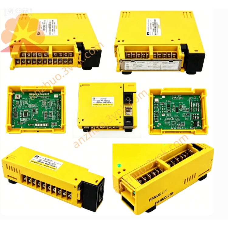
A06B-6130-K20A is a specialized 6‑pin power/signal hybrid connector for FANUC βi‑series 200V servo amplifiers (A06B-6130‑Hxxx). It is designed for combined power and low‑level signal connections in compact servo drive systems, supporting both motor power and control signal integration.
Description
A06B-6130-K20A is a specialized 6‑pin power/signal hybrid connector for FANUC βi‑series 200V servo amplifiers (A06B-6130‑Hxxx). It is designed for combined power and low‑level signal connections in compact servo drive systems, supporting both motor power and control signal integration.
Part Information
Part Number: A06B-6130-K20AType: 6‑pin hybrid (power + signal) connectorApplicable Series: βiSV / βiSVM (200V class, A06B-6130‑Hxxx)Manufacturer: FANUCFunction: Integrated motor power (U/V/W) and control signal wiringMNR (FANUC ref): A63L-0001-0812/CRM/R06HA
Electrical Specifications
Maximum rated voltage: 250V ACContinuous rated current: 5A per pin (power pins); 2A per pin (signal pins)Applicable wire size: 0.5mm²–1.0mm² (20–24 AWG) for power; 0.3mm²–0.5mm² (24–28 AWG) for signalsContact resistance: ≤10mΩ (power); ≤15mΩ (signal)Insulation resistance: ≥50MΩ at 500V DCWithstand voltage: 1500V AC for 1 minuteSignal compatibility: FANUC standard servo control signals (SON, E‑STOP, ALM)
Mechanical & Material
Housing material: Flame‑retardant thermoplastic (UL94 V‑0), blackContact material: Tin‑plated phosphor bronze (power); gold‑plated phosphor bronze (signal)Locking method: Screw lock (M2.5), vibration‑resistantApproximate dimensions: 22mm × 28mm × 10mmApproximate weight: 6gKeying feature: Unique polarization to prevent misinsertion
Compatible Amplifiers
βiSV‑4A, βiSV‑20A, βiSV‑40A, βiSV‑80AβiSVM‑40i, βiSVM‑80i, βiSVM‑160i (A06B-6130‑Hxxx series)
Features
Integrated 6‑pin design combining power and control signalsDual contact plating (tin/gold) for optimal power/signal performanceHigh‑temperature and flame‑retardant housing for industrial environmentsEnhanced vibration resistance for machine tool applicationsCompact footprint saves cabinet spaceTool‑free field wiring and replacement
Installation Instructions
Disconnect all AC and DC power before wiring.
Strip wire insulation to 6–7mm for power wires, 5–6mm for signal wires.
Assign wires to 6 pins: U, V, W (power); SON, E‑STOP, ALM (signal).
Tighten M2.5 screws to 0.4–0.5N·m (power) and 0.3–0.4N·m (signal).
Align polarized plug with amplifier port and seat firmly until click.
Verify tightness, insulation, and keying alignment before power‑on.
Safety Precautions
Strictly observe voltage and current ratings to avoid overheating.Separate power and signal wiring from high‑noise cables (e.g., motor leads).Use only insulated, stranded copper wires per AWG specifications.Inspect connectors for damage, deformation, or corrosion before use.Ensure proper grounding of shielded wires to prevent EMI interference.
Related Parts
A06B-6130-K200/K201: UVWPE power connectorsA06B-6130-K202: Discharge resistor connectorA06B-6130-K203: 3‑pin control signal connectorA06B-6130-K204: 6‑pin encoder connectorA06B-6130-Hxxx: βi servo amplifiers
Get a Quote