A06B-6115
Description
1. General Information
2. Model & Description
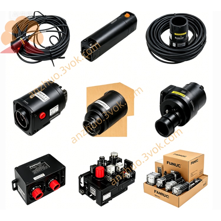
A06B-6115-H001:SVPM1-05 single-axis servo amplifier, compact panel-mount type.
A06B-6115-H003:PSMR-3i power supply module, 3.8kW regenerative type.
A06B-6115-H006:PSMR-5.5i power supply module, 5.5kW regenerative type.
Common features across models:Integrated cooling fan, panel-mount installation, compatible with FANUC αi servo motors and CNC systems.
3. Electrical Specifications
A06B-6115-H003 (PSMR-3i)
Input Voltage:3-phase 200–240V AC, 50/60Hz.
Rated Input Current:14.5A @ 200V.
Output Voltage:283–339V DC.
Rated Output Power:3.8kW.
Regeneration Function:Returns braking energy to AC power supply.
A06B-6115-H006 (PSMR-5.5i)
Input Voltage:3-phase 200–240V AC, 50/60Hz.
Rated Output Power:5.5kW.
Output Voltage:283–339V DC.
A06B-6115-H001 (SVPM1-05)
Input Voltage:3-phase 200–230V AC.
Number of Axes:1-axis servo control.
Cooling Method:Internal fan cooling.
4. Mechanical & Environmental
Material:Rugged industrial plastic and metal casing, dust and oil resistant.
Mounting:Panel-mount type, vertical installation in control cabinet.
Operating Temperature:0°C to +55°C.
Storage Temperature:-20°C to +70°C.
Cooling:Integrated axial fan, maintains stable operating temperature.
Weight:Approx. 1.9kg (H003), 2.5kg (H006).
5. Compatibility
Compatible Motors:FANUC αi series servo motors and spindle motors.
CNC Systems:FANUC 0i, 30i/31i/32i series CNC controllersFANUC.
Amplifiers:αi SV series servo amplifiers, αi SP series spindle amplifiers.
Communication:Supports FANUC FSSB high-speed serial bus for seamless system integration.
6. Protection & Diagnostics
Overcurrent Protection:Detects overcurrent in main circuit, triggers alarm AL-1.
Overheat Protection:Monitors heat sink temperature, triggers alarm AL-3.
Overvoltage/Undervoltage Protection:Monitors DC bus voltage, triggers AL-4 (undervoltage) or AL-7 (overvoltage).
Fan Fault Protection:Detects cooling fan stop, triggers alarm AL-2.
Phase Loss Protection:Detects input power phase loss, triggers alarm AL-E.
LED Diagnostics:Built-in status LEDs for real-time fault indication and maintenance.
7. Installation & Wiring
Power off the system and implement lockout/tagout to prevent electric shock.
Mount the module vertically on the cabinet panel with specified mounting screws, ensuring adequate ventilation around the unit.
Connect 3-phase AC power input to the L1/L2/L3 terminals, and ground the PE terminal properly.
Connect DC bus output to servo/spindle amplifiers via DC+ and DC- terminals.
Connect control cables (FSSB, emergency stop) to the designated connectors.
Verify all connections are secure and correct before restoring power.
After power-on, check LED status and confirm no alarms are present.
8. Safety & Warnings
Warning:Only qualified electrical personnel should perform installation, wiring, and maintenance.
Warning:High voltage exists inside the module; wait at least 10 minutes after power-off before opening the cover to avoid electric shock.
Caution:Do not connect incompatible motors or amplifiers, which may cause equipment damage.
Caution:Ensure proper ventilation to prevent overheating and premature failure.
Maintenance:Regularly clean the cooling fan and heat sink to maintain cooling efficiency; replace faulty fans promptly.
9. Applications
CNC machining centers, lathes, milling machines.
Industrial robots and automated assembly lines.
Precision positioning systems and multi-axis motion control equipment.
High-speed and high-precision industrial automation applications.
Get a Quote