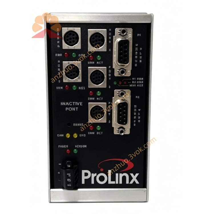
5302-MBP-MCM4
Description
1. Product Overview
2. Main Features
Standard Modbus Plus slave communication function, seamlessly access Modbus Plus network
Built-in 4 independent isolated Modbus serial ports, each channel works independently
Each port supports Modbus RTU master and slave dual operation modes
Support RS-232, RS-422, RS-485 multiple physical interface selection
Rich Modbus function codes support, complete reading and writing of coil and register data
Massive internal data buffer area, convenient cross-network data mapping transmission
Independent communication parameter configuration for each channel, flexible on-site matching
Powerful bus fault diagnosis and communication status monitoring function
Industrial surge isolation design, stable operation in complex industrial interference environment
Easy configuration operation, support online debugging and firmware upgrade
3. Technical Specifications
3.1 Power Supply
3.2 Modbus Plus Interface
3.3 Four-channel Modbus Serial Interface
3.4 Environmental Parameters
3.5 Physical Parameters
4. LED Status Indication
5. Installation and Wiring Steps
Install the gateway firmly on the control cabinet DIN rail
Connect 24VDC DC power supply correctly according to wiring requirements
Connect Modbus Plus communication cable to DB9 interface to access upper network
Connect different Modbus RTU field devices to four independent serial channels
Use professional configuration software to set Modbus Plus node address
Configure communication mode, baud rate and station address for each Modbus channel
Set cross-network data mapping relation, download parameters and complete communication debugging
6. Communication Function
Realize Modbus Plus system centralized reading data of four groups Modbus RTU equipment
Distribute control commands from Modbus Plus host to each Modbus field terminal equipment
Realize unified networking management of multi-batch Modbus instruments, sensors and frequency converters
Collect field equipment running status, fault information and upload to upper control network
Single channel fault will not affect the normal communication of other channels
7. Application Scope
Old Modbus Plus PLC system expansion and equipment networking transformation
Factory workshop multi-point Modbus RTU instrument centralized acquisition system
Water treatment, environmental protection industry multi-channel field bus integration project
Packaging, printing machinery industry old control system function expansion
Energy monitoring system multi-site Modbus equipment unified access scheme
Distributed industrial sensor data remote centralized monitoring system
8. Safety Notes
All wiring operations must be completed under power-off state
Modbus serial bus uses shielded twisted pair wire to enhance anti-interference ability
Reasonably set terminal resistance according to field bus wiring length
Keep communication parameters consistent at both ends of Modbus communication
Avoid laying signal lines together with high-power power lines
Professional automation technicians shall complete parameter configuration and network debugging
Get a Quote