5301-MBP-ASCII
Description
1. Product Overview
Part Number: 5301-MBP-ASCII
Manufacturer: ProSoft Technology
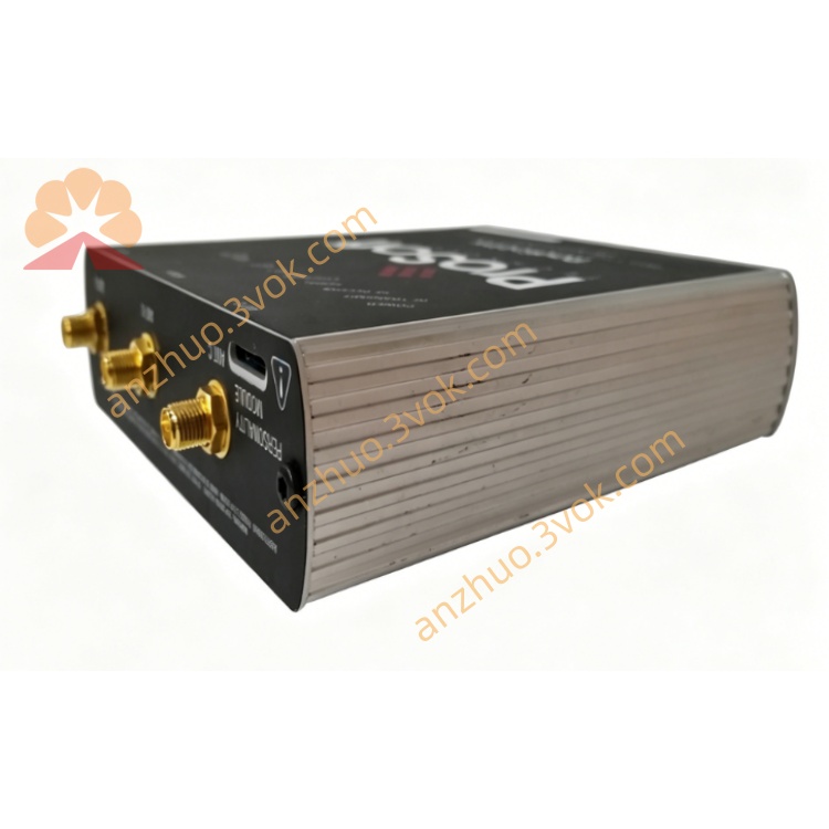
Product Type: Industrial DIN‑rail mounted protocol gateway
Function: Bridges Modbus Plus (MBP) industrial network with ASCII‑based serial devices (RS‑232/422/485). Enables legacy Modbus Plus PLCs to exchange ASCII text data with printers, displays, scanners, weigh scales, and custom serial instruments.
2. Main Features
Modbus Plus Interface: Full master/slave support, DB‑9F port, 1–247 node address range。
ASCII Serial Support: RS‑232/422/485, configurable baud rate (300–115.2k), parity, data/stop bits。
Flexible Modes: Receive‑only, transmit‑only, transmit‑receive;supports user‑defined termination characters (CR/LF, ETX, etc.)。
Data Mapping: Maps Modbus Plus register data to ASCII strings and vice versa;configurable start/end addresses。
Handshaking: RTS/CTS, XON/XOFF, or no handshake;adjustable RTS on/off delays。
Diagnostics: Real‑time status LEDs, error counters, and timeout monitoring。
Industrial Grade: Isolated serial ports, surge protection, wide temperature range。
Configuration: ProSoft Configuration Builder (PCB) software;save/load settings, online monitoring。
3. Technical Specifications
3.1 Power Supply
Rated Voltage: 24 VDC
Range: 18–36 VDC
Max Power: ≤15 W
Redundancy: Dual power input support
3.2 Modbus Plus Interface
Connector: DB‑9F
Protocol: Modbus Plus (master/slave)
Network Speed: 1 Mbps
Node Address: 1–247 (software configurable)
3.3 ASCII Serial Interface
Ports: 1 × RS‑232/422/485 (DB‑9 or terminal block)
Baud Rate: 300, 600, 1200, 2400, 4800, 9600, 19.2k, 38.4k, 57.6k, 115.2k
Data Bits: 7 or 8
Stop Bits: 1 or 2
Parity: None, Odd, Even
Termination: CR, LF, ETX, user‑defined bytes, or fixed length
3.4 Environmental
Operating Temp: −20°C to +60°C
Storage Temp: −40°C to +85°C
Humidity: 5%–95% (non‑condensing)
Certifications: CE, UL, CSA
3.5 Physical
Mounting: 35 mm DIN rail
Dimensions: 120 × 80 × 35 mm
Protection: IP30
4. LED Indicators
PWR: Solid = power OK
RUN: Blinking = 正常运行
MBP: Blinking = Modbus Plus activity
ASC: Blinking = ASCII serial activity
ERR: Solid = fault (communication/configuration)
5. Installation & Wiring
Mount on DIN rail in cabinet.
Connect 24 VDC power (observe polarity).
Connect Modbus Plus cable to DB‑9F port.
Wire ASCII device to serial port (RS‑232/422/485 as required).
Set node address via DIP switches or software.
Configure with PCB software: serial parameters, data mapping, modes.
Download configuration and test communication.
6. Communication Functions
Modbus Plus → ASCII: Convert register values to ASCII strings (e.g., “TEMP=25.5”).
ASCII → Modbus Plus: Parse incoming ASCII data (e.g., “WEIGHT=100”) into registers.
Triggered Transmit: Send ASCII messages on value change or cyclic basis.
Timeout Handling: Configurable RX/TX timeouts with error logging.
Data Formatting: Swap bytes, add checksum (LRC), or pad strings。
7. Application Scope
Legacy System Integration: Connect Modbus Plus PLCs to modern ASCII devices.
Factory Automation: Link PLCs to printers, operator terminals, barcode scanners.
Process Control: Interface with weigh scales, flow meters, and serial analyzers.
Building Automation: Connect HVAC controllers to ASCII displays.
Retrofit Projects: Upgrade old Modbus Plus systems without replacing PLCs。
8. Safety Precautions
Power Off: All wiring must be done with power disconnected.
Cable Separation: Keep serial cables away from high‑voltage power lines.
Grounding: Ensure proper grounding to avoid ESD damage.
Environment: Do not operate outside specified temperature/humidity ranges.
Configuration: Only qualified personnel should configure and troubleshoot。
Get a Quote