5202-DFNT-GRCM4
Description
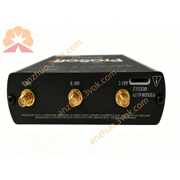
1. Product Overview
2. Main Features
Fully conform to standard EtherNet/IP protocol, support client and server operation modes
Four independent isolated general radio modem communication ports, each channel works separately
Support RS-232, RS-422, RS-485 multi-physical interface selection for each serial channel
Adapt to various brands of industrial wireless radio modems, transparent data transmission
Independently configurable baud rate, data bit, stop bit and parity for each channel
Powerful EtherNet/IP tag and serial data mapping function
Built-in wireless communication timeout detection and automatic reconnection function
Industrial grade surge isolation design, strong anti-interference ability for outdoor wireless environment
Support real-time running status monitoring and remote parameter configuration
Wide temperature design, suitable for field outdoor and harsh industrial sites
3. Technical Specifications
3.1 Power Supply
3.2 EtherNet/IP Ethernet Interface
3.3 Four-Channel General Modem Serial Interface
3.4 Environmental Parameters
3.5 Physical Parameters
4. LED Status Definition
5. Installation and Wiring Steps
Fix the gateway firmly on cabinet DIN rail
Connect qualified 24VDC DC power supply correctly
Connect Ethernet cable to RJ45 port to access upper EtherNet/IP control system
Connect four channels of serial wiring to corresponding industrial radio modems respectively
Use configuration software to set Ethernet IP address and serial communication parameters
Match the same communication parameters with remote wireless modem terminals
Complete data mapping configuration, download parameters and finish wireless debugging
6. Core Communication Functions
Collect remote site data through wireless radio modems and upload to EtherNet/IP host
Issue centralized control commands from upper system to distributed wireless field equipment
Realize long-distance point-to-point and point-to-multipoint wireless data transmission
Support multi-site distributed sensor data centralized acquisition management
Automatically identify wireless signal disconnection and realize automatic reconnection recovery
7. Application Scope
Oil field, gas field long-distance wireless data monitoring system
Water conservancy pipeline, river basin distributed remote monitoring project
Mining area outdoor wireless equipment centralized control system
Remote meteorological environmental monitoring data transmission system
Large farm, pasture distributed equipment wireless networking management
Industrial scattered site equipment wireless transformation and Ethernet unified access
8. Safety Operation Regulations
All wiring operations must be performed under power-off condition
Outdoor wireless signal lines must use shielded cables and do good lightning protection measures
Keep the communication parameters of local gateway and remote modem completely consistent
Avoid installing the equipment in strong electromagnetic interference area
Regularly check power supply stability and wireless signal strength
Professional technicians shall complete parameter matching and wireless network debugging
Get a Quote