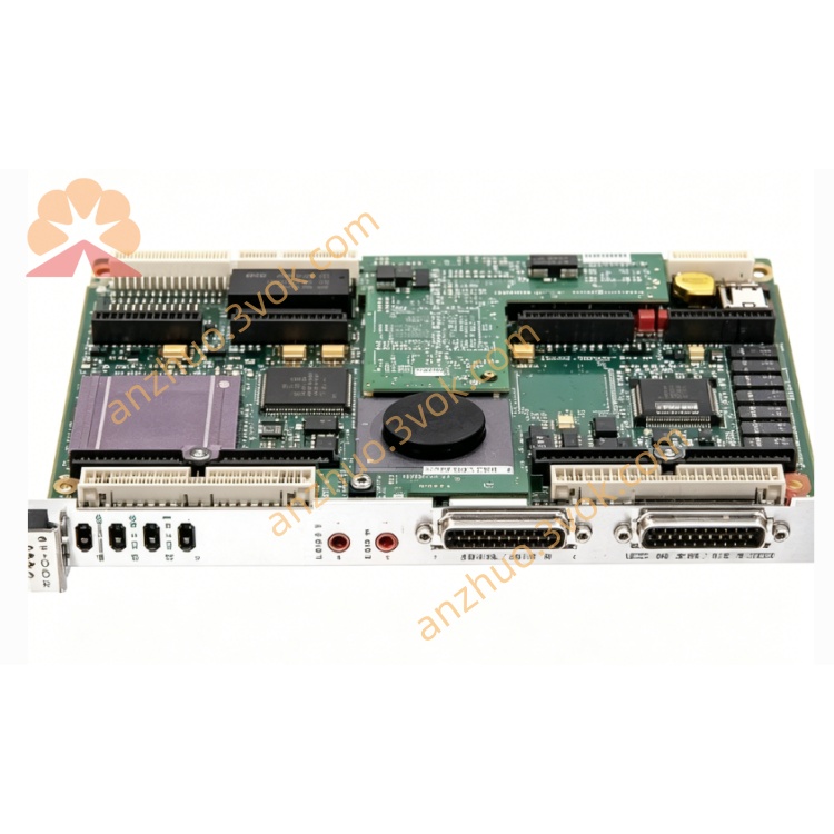
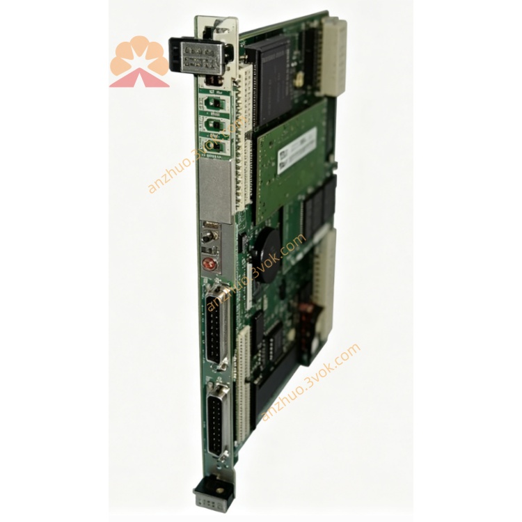
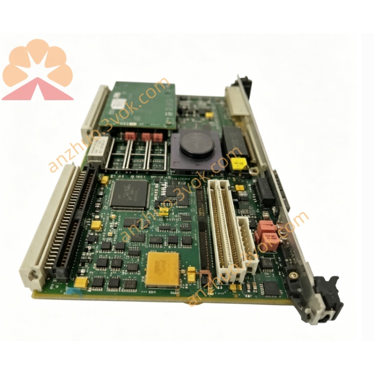
Motorola MVME162-012 VMEbus SBC MC68LC040 Industrial Embedded CPU Board
Description
Technical Manual (Condensed English Version)
1. General Description
2. Core Specifications
Processor: Motorola MC68LC040 @ 25 MHz (standard, no FPU); optional MC68040 @ 25 MHz (with FPU)
Cache: 8 KB internal cache + MMU
DRAM: 4 MB parity‑checked DRAM (expandable to 8 MB)
SRAM: 512 KB battery‑backed SRAM
Flash: 1 MB Flash (for 162BUG firmware)
NVRAM/RTC: 8 KB NVRAM + Real‑Time Clock, battery‑backed
3. Onboard Interfaces
Ethernet: Onboard 10 Mbps Ethernet (AUI/10BASE‑T, with DMA)
IndustryPack (IP): 4 IP slots (single‑width) or 2 double‑width IP modules
Serial Ports:
1 × Console (EIA‑232‑D)
1 × Configurable (EIA‑232/422/530 selectable)
VMEbus: A32/D32, master/slave, system controller capable
Front Panel: 8 LEDs (FAIL, STAT, RUN, LAN, etc.), RESET and ABORT switches
NOT included: SCSI interface (unlike 011A)
4. Mechanical & Environmental
Form Factor: 6U VMEbus, single slot
Operating Temperature: 0°C ~ +55°C (industrial)
Storage Temperature: -40°C ~ +85°C
Humidity: 5%–95% non‑condensing
5. Firmware & Software
Boot Monitor: 162BUG (Motorola proprietary)
Supported OS: VxWorks, LynxOS, OS‑9, pSOS+, VRTX, OpenBSD/mvme68k, NetBSD/mvme68k
Functions: Boot, self‑test, memory/VME mapping, serial console, Ethernet/IP configuration
6. MVME162 Series Comparison (Key Models)
MVME162‑010A: IP slots + dual serial, no SCSI/Ethernet
MVME162‑011A: SCSI‑2 + 512KB SRAM, no Ethernet/IP
MVME162‑012: Ethernet + IP slots, no SCSI
MVME162‑013: SCSI + Ethernet, no IP slots
7. Typical Applications
VMEbus industrial automation & DCS
Test & measurement systems (ATE)
Embedded control with Ethernet and I/O expansion via IP modules
Upgrade/replacement for legacy MVME162 systems
8. Maintenance Notes
Replace backup battery periodically to preserve SRAM/RTC data
Configure VMEbus master/slave via jumpers
Check Ethernet termination and IP module seating before power‑on
Get a Quote