MVME162-031
Product Introduction
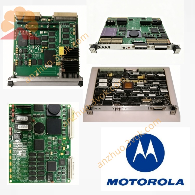
MVME162-031 is Motorola original 6U single-height VMEbus single-board computer belonging to classic MVME162 series, MC68040 CPU configuration version with full onboard I/O including Ethernet, SCSI and serial ports, widely deployed in legacy industrial VME rack control system, nuclear auxiliary control, locomotive vehicle control, military measurement equipment and industrial test bench real-time master controller.
Description
Model Interpretation
MVME = Motorola VME single board computer family162 = 68040 core VME SBC product series031 = fixed factory configuration code: MC68040(with FPU&MMU), 8MB DRAM, 1MB Flash, onboard Ethernet+SCSI+dual serial+parallel port full-option hardware specification.
Technical Specifications
Processor & Cache
CPU: MC68040 32-bit CISC, 25MHz, integrated MMU+FPU; built-in 8KB unified cache
Memory Configuration
Onboard DRAM: 8MB parity-check DRAMFlash ROM: 1MB onboard flash for boot monitor firmwareBackup SRAM: 512KB battery-backed SRAMNVRAM+RTC: 8KB nonvolatile memory with onboard clock, powered by replaceable coin cell battery
Electrical & Ambient Parameter
Power supply: +5V/+12V/-12V taken from VME backplane P1 connector, typical power consumption 9.5WOperating temperature: 0℃~+55℃ standard air cooling; extended industrial version -40℃~+85℃Storage temperature: -45℃~+85℃, humidity 5%~95%RH non-condensing, conform to industrial CE Class A standard
Interface and communication configuration
Front panel onboard ports
1×DB25 console RS232 serial port (fixed DCE mode)1×DB9 configurable serial port, switchable RS232/RS4221×DB25 parallel print portStatus indicator LED: RUN, FAULT, LAN, SCSI, VME power indicator; RESET/ABORT manual push button on front edge
Backplane & expansion bus
VMEbus P1/P2 edge connector, VMEchip2 control chip, support A16/A24/A32 address space, D16/D32/D64BLT data transmission, work as VME master/slave/system controller with hardware DMA channelOnboard full-option peripherals:10Mbps Ethernet (Intel 82596CA controller, 32-bit DMA), narrow SCSI (NCR53C710 chip for external disk drive)4×IndustryPack IP module expansion slots via P2 rear transition board; optional PC/104 expansion interfaceExternal I/O expansion via MVME712 series transition daughterboard connected on P2 connector
Core Function
Preloaded onboard debug monitor firmware, supports power-on self-test POST, hardware fault diagnosis, firmware download and flash programming; compatible OS-9, VRTX, LynxOS, pSOS classic real-time operating system
Serve as VME rack main controller, manage all slave VME I/O modules to realize synchronous data acquisition, closed-loop logic control and inter-board communication via VME bus interrupt mechanism
Realize local data storage via external SCSI hard disk; complete field data upload and remote debugging through onboard Ethernet
Built-in independent hardware watchdog timer, auto-trigger system reset upon program runaway or system crash; continuous onboard peripheral self-check with corresponding LED fault alarm
Applicable scenarios
Old-type thermal power DCS auxiliary cabinet, railway locomotive vehicle control unit, military ground test instrumentation, hydraulic servo durability test bench, traditional ship auxiliary monitoring VME control cabinet.
Operation and maintenance instructions
Power off entire VME chassis before plugging/unplugging the board or IP/transition daughterboard to avoid bus surge damageReplace onboard RTC backup battery every 3~5 years to prevent configuration parameter loss after power failureSCSI bus must install matching terminal resistance at both ends of cable; regularly clean front panel port dust and P1/P2 edge connector oxidationProhibit hot plug SCSI hard disk and Ethernet cable during equipment running; store spare board under dry constant-temperature environment away from corrosive gas and oil mist
Get a Quote