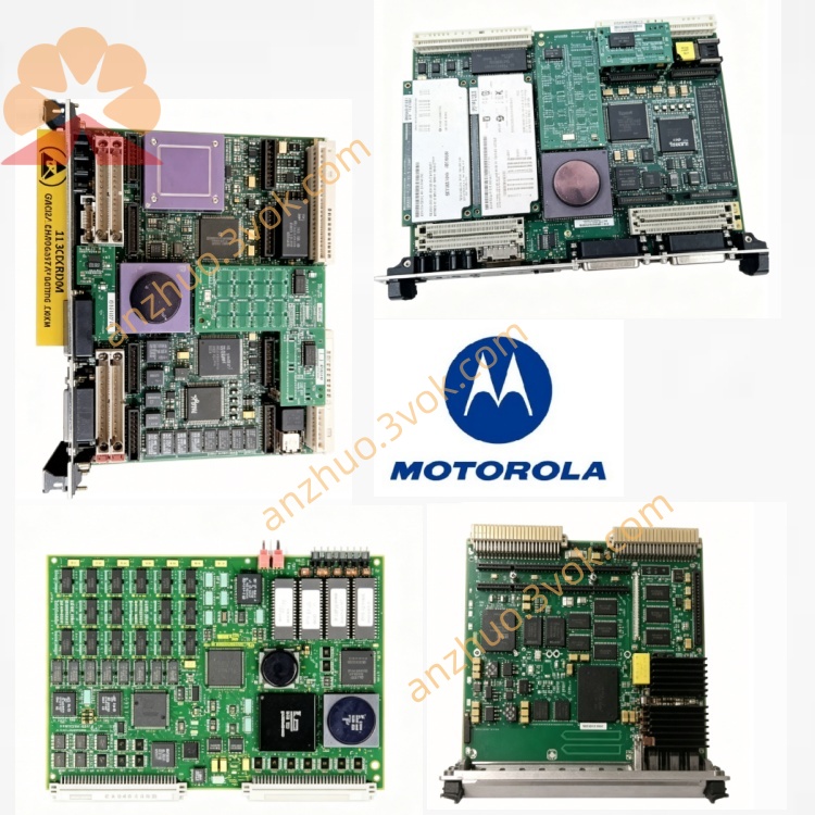
MVME5500 MOTOROLA VME Single Board Computer
Description
Model Interpretation
MVME:Motorola VME single-board computer product family
5500:High-end PowerPC74xx generation VME controller coding; suffix digits such as -0163 stand for customized memory/flash configuration version。
Technical Specifications
Processor & Cache
CPU:MPC7455/MPC7457 PowerPC, main frequency 1.0GHz~1.3GHz, embedded AltiVec floating-point coprocessor for high-speed algorithm operation
Cache:512KB on-chip L2 cache, optional 2MB external L3 cache
Memory & Onboard Storage
SDRAM:ECC DDR SDRAM, onboard standard 512MB, expandable to max 2GB via memory mezzanine card, 133MHz memory bus
Flash:Dual bank onboard soldered Flash (8MB+32MB standard), optional up to 512MB Flash, solidified MOTLoad boot firmware
Electrical & Environmental Rating
Input power:+5V from VME backplane bus, typical power consumption 22W
Operation temperature:0℃~+55℃ (forced air cooling); Storage:-40℃~+85℃
Humidity:5%~95%RH non-condensing; anti-vibration 1G 5~100Hz, comply CE/UL/FCC Class A EMC certification
Interface & Communication Configuration
Front Panel Onboard Ports
1×RJ45 Gigabit Ethernet (10/100/1000Mbps)
1×RJ45 10/100BASE-TX Fast Ethernet
2×DB9 RS232/422 asynchronous serial debug ports
Backplane & Expansion Bus
VME Bus:VME64 compliant via P1/P2 edge connectors, Universe-II VME bridge chip, 64-bit VME data transmission
Dual independent 64-bit PCI 33/66MHz buses, 2×PMC expansion slots (IEEE1386.1 standard), each PMC supports front/rear P2 routing I/O; reserved PrPMC processor mezzanine expansion interface, expandable SCSI, multi-serial, analog acquisition via PMC cards
Auxiliary Circuit
Built-in watchdog timer, hardware EEPROM for system parameter storage, general-purpose GPIO pins configurable as interrupt input; onboard MOTLoad bootloader for POST diagnosis, system initialization and OS boot management
Core Functions
Real-time operating system supporting: VxWorks, Embedded Linux, LynxOS, pSOS; MOTLoad firmware realizes power-on self-test, hardware diagnosis, program download and boot configuration
Dual independent PCI+PMC expansion architecture, flexible extension of fieldbus (CAN/Profibus), data acquisition and communication functions without occupying extra VME slots
Complete VME master/slave arbitration function, works as system VME bus controller for multi-card VME rack synchronous control
Hardware fault self-diagnosis via front panel RUN/FAULT/COM LED indicators, watchdog automatic reset upon system crash
Applicable Scenarios
Railway vehicle traction control, aerospace ground test bench, nuclear power auxiliary DCS system, ship-borne automation equipment, large industrial high-speed data acquisition system, military radar signal processing unit
Operation & Maintenance Instruction
Before PMC card hot swapping, cut off chassis power supply to avoid PCI bus voltage surge damaging onboard chip
Configure front/rear I/O routing via onboard jumper caps (J102~J110); jumper 1-2 for front panel IO, jumper 2-3 for P2 rear transition board IO
Regularly clean chassis air duct and board surface dust to prevent overheating under long-time full-load operation
Modify VME interrupt vector within 0xC0~0xFF range during driver development to match MVME5500 VME controller interrupt specification
Store system mirror into onboard Flash via MOTLoad command for offline startup after power failure
Get a Quote