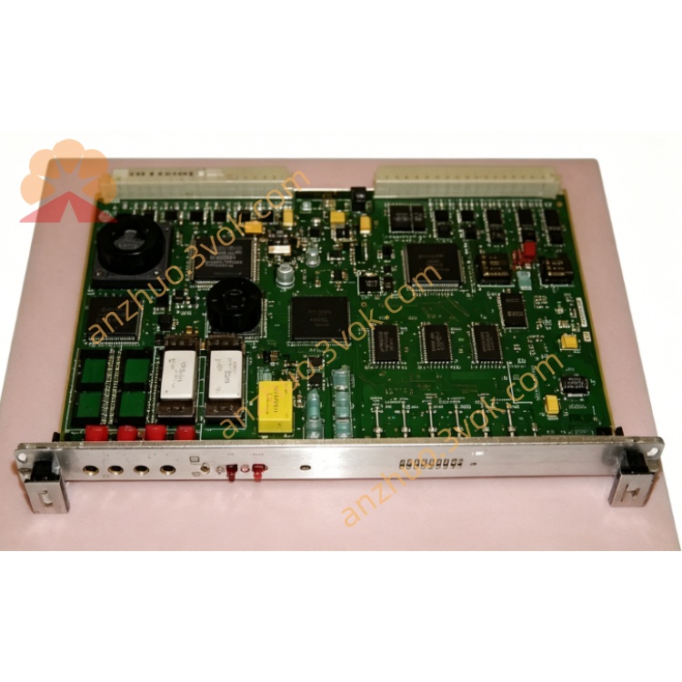
Motorola MVME147-011 VMEbus Single Board Computer MC68030 CPU Card
Description
1. General Description
2. Key Differences from MVME147‑010
CPU/FPU: 25 MHz (010 = 16 MHz)
Ethernet: Onboard AUI Ethernet (010 = No Ethernet)
DRAM: 4 MB (same as 010, no parity)
3. Key Features
Processor:
MC68030 @ 25 MHz (32‑bit, MMU, 256B cache)
MC68882 FPU @ 25 MHz (IEEE 754 floating‑point)
Memory:
DRAM: 4 MB standard (no parity)
EPROM: 4 × 32‑pin sockets, up to 4 MB total (16‑bit wide)
SRAM: 4 KB battery‑backed (data retention)
RTC: Battery‑backed time‑of‑day clock/calendar
Onboard I/O:
4 × RS‑232‑D serial ports (Z8530 controller)
1 × 8‑bit Centronics parallel printer port
1 × SCSI interface (WD33C93, DMA capable)
1 × AUI Ethernet (10 Mbps, external transceiver)
VMEbus Interface:
Compliance: ANSI/VITA 1‑1994 VME64 (IEEE 1014)
Address: A16/A24/A32
Data: D08/D16/D32
Mode: Master + Slave
System controller: SYSCLK, arbiter, reset, BTO
Timers & Control:
2 × 16‑bit tick timers (periodic interrupts)
1 × watchdog timer
2 × software interrupts
Status & Switches:
LEDs: SCON, RUN, FAIL, STATUS
Switches: RESET, ABORT; remote RESET connector
Power Supply:
+5 VDC, ±12 VDC (VMEbus standard)
4. Technical Specifications
4.1 Processor / FPU
CPU: MC68030 @ 25 MHz, 32‑bit, MMU, 256B cache
FPU: MC68882 @ 25 MHz, IEEE 754 compatible
4.2 Memory
DRAM: 4 MB, no parity, single‑cycle access
EPROM: 4 MB max (4 sockets, 16‑bit)
SRAM: 4 KB, battery‑backed
RTC: Battery‑backed, Y2K compliant
4.3 I/O Interfaces
Serial: 4 × RS‑232‑D (EIA‑232), Z8530
Parallel: 1 × Centronics‑compatible (8‑bit)
SCSI: 1 × asynchronous SCSI, WD33C93, DMA
Ethernet: 1 × AUI 10 Mbps (external transceiver)
4.4 VMEbus
Architecture: VME64 (A32/D32)
Master/Slave: Full master + slave
System controller: Yes (jumper selectable)
4.5 Electrical
Voltage: +5 VDC, ±12 VDC
Logic: 5 V TTL compatible
4.6 Mechanical
Form Factor: 6U VME
Size: 233 mm × 160 mm
Mounting: Standard VME chassis slot
4.7 Environmental
Operating Temp: 0 °C to +55 °C
Storage Temp: ‑20 °C to +70 °C
Humidity: 5%–95% RH, non‑condensing
4.8 OS Support
VxWorks (legacy), Motorola VERSAdos, NetBSD/mvme68k, custom RTOS, bare‑metal
5. MVME147 Series Variations
MVME147‑010: 16 MHz, 4 MB DRAM, no Ethernet, SCSI
MVME147‑011: 25 MHz, 4 MB DRAM, Ethernet + SCSI
MVME147‑012: 25 MHz, 8 MB DRAM, Ethernet + SCSI
MVME147‑013: 25 MHz, 16 MB DRAM, Ethernet + SCSI
Get a Quote