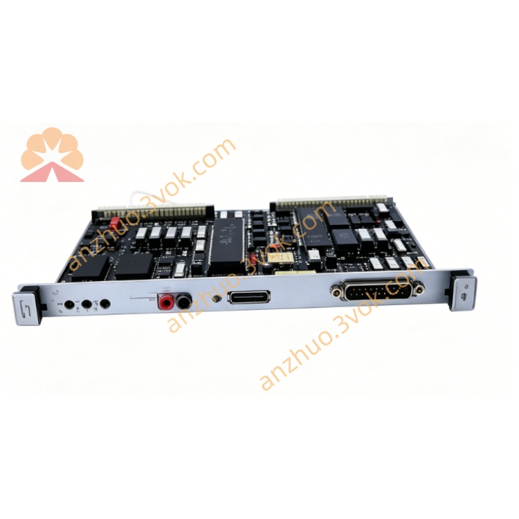
Motorola MVME117A VMEbus Single-Board Computer MC68010 CPU Module
Description
1. General Description
2. Key Features
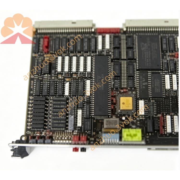
Processor:
Standard: Motorola MC68010 @ 10 MHz
Option: MC68030 @ 25 MHz (32‑bit, MMU)
Memory:
RAM: 2 MB DRAM standard (with parity)
EPROM/ROM: 128 KB (four 28‑pin sockets, 8K×8~64K×8)
CMOS RAM: 2 KB battery‑backed (expandable to 8 KB)
Onboard I/O:
1 × multi‑protocol RS‑232C serial (P2 connector)
1 × front‑panel debug serial port (J6, terminal only)
2 × 8‑bit parallel ports (Centronics compatible, via P2)
1 × SCSI bus interface (P2 connector)
VMEbus Interface:
A16/A24 address, D16/D32 data
Master + Slave mode, VMEbus compliant
System controller functions (SYSCLK, BTO, arbiter, reset)
Timers & Control:
MC68B40 triple 16‑bit timers: tick, watchdog, user timer
Battery‑backed RTC (time‑of‑day clock/calendar)
Status Indicators:
RUN, HALT, FAIL LED indicators
Power Supply:
+5 VDC, ±12 VDC (VMEbus standard)
3. Technical Specifications
3.1 Processor
CPU: Motorola MC68010 (10 MHz) / MC68030 (25 MHz)
Architecture: 32‑bit internal, 16/32‑bit external bus
3.2 Memory
DRAM: 2 MB (zero‑wait‑state, parity option)
EPROM: 128 KB (4 sockets)
CMOS RAM: 2 KB (battery‑backed)
3.3 I/O Interfaces
Serial: 2 × RS‑232C (1 × P2, 1 × front debug)
Parallel: 2 × 8‑bit (Centronics)
SCSI: 1 × SCSI (P2)
3.4 VMEbus
Address: A16 / A24
Data: D16 / D32
Mode: Master / Slave
System controller: jumper‑enable
3.5 Electrical
Voltage: +5 VDC, ±12 VDC
Logic: 5 V TTL compatible
3.6 Mechanical
Form Factor: 6U VME
Size: 233 mm × 160 mm
Mounting: Standard VME chassis slot
3.7 Environmental
Operating Temp: 0 °C to +55 °C
Storage Temp: ‑20 °C to +70 °C
Humidity: 5%–95% RH, non‑condensing
3.8 OS Support
Motorola VERSAdos, VxWorks (legacy), custom RTOS, bare‑metal
4. Typical Applications
Legacy DCS / SIS system main controller
Industrial automation & process control
Military / aerospace embedded systems
VMEbus test & measurement systems
Real‑time embedded control equipment
Get a Quote