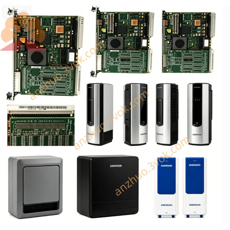
Emerson Ovation 5X00063G01 DCS Hot-Swappable I/O
The 5X00063G01 is a standard plug-in I/O module designed exclusively for the Emerson Ovation distributed control system. It acts as the key signal interaction gateway linking field sensors, transmitters, field actuators and system central controllers in process industrial automation loops. Integrated complete multi-level self-diagnostic circuits monitor power supply state, bus communication quality and each channel operating condition in real time, while front panel LED lamps directly display working status for fast on-site fault location. This module passes strict anti-electromagnetic interference, vibration resistance and high-low temperature aging verification and holds CE and UL safety certifications. Each channel supports flexible parameter setup via the Ovation engineering workstation to fit diverse field signal types. It is fully compatible with original racks, backplanes and matched terminal bases and supports hot swapping without cabinet power cut, which effectively lowers unplanned system downtime and ensures long-term reliable operation under harsh industrial conditions.
Description
3.1 Technical Specifications
The module obtains working power from the cabinet backplane bus. Its operating temperature range is 0℃ ~ +60℃, storage temperature ranges from -25℃ ~ +70℃, and applicable relative humidity is 5%~95% non-condensing. Every signal channel adopts independent electrical isolation design, equipped with built-in surge suppression and loop short-circuit fuse protection. It adopts standard rack plug-in installation structure and supports online hot swapping during system normal operation. The designed service life under rated working conditions exceeds 10 years. It complies with CE EMC and LVD international standards and can be perfectly matched with all standard Ovation controller racks and supporting backplane assemblies.
3.2 Installation Guidelines
Check that the target rack slot is vacant and intact, and confirm the backplane bus golden fingers have no bending, oxidation or foreign attachments. Align the module side guide rails with the rack chutes, push the module horizontally and steadily inward until the rear connector fully locks and closely connects to the backplane interface. Tighten the fixing screws on the upper and lower sides of the front panel sequentially to avoid poor contact caused by long-term equipment vibration. Reserve enough surrounding space for heat dissipation, and do not stack cables or other components to block the module ventilation gaps.
3.3 Wiring Requirements
Distinguish power terminals, signal input channels, signal output channels and communication terminals strictly according to the silkscreen marks on the supporting terminal base. Select shielded twisted-pair cables with proper wire cross-section according to actual loop current, and firmly crimp cable terminals to avoid poor contact and signal drift. Separate strong-current power cables and weak signal cables during wiring routing to reduce crosstalk interference. Neatly bind scattered harnesses with cable ties and fix them securely to prevent pulling and abrasion during long-term running. Complete full-circuit continuity test and insulation resistance inspection after wiring, and confirm no short circuit, reversed polarity or misconnection exists before power-on trial operation.
3.4 Software Configuration Steps
Log in to the Ovation engineering workstation with authorized engineer account and open the dedicated configuration software. Create a new I/O point list, select module model 5X00063G01 from the hardware library, and bind the actual physical rack number and slot address. Configure signal type, measuring range, alarm threshold and logic attributes independently for each channel according to field instrument access requirements. Fully compile the configuration file and download it to the corresponding DCS controller, execute online synchronization and verify real-time signal acquisition accuracy of each channel. Perform no-load power-on test first, then conduct joint debugging with actual loads to confirm the module output responds accurately and timely to upper control commands.
3.5 LED Indicator Description
The POWER indicator keeps solid green under normal power supply; it turns off or lights red when slot power supply is abnormal or the module internal power circuit fails. The COMM indicator flashes green periodically during normal communication with the controller; constant red light means communication interruption, address mismatch or backplane bus fault. Each channel has an independent indicator light that flashes green for normal signal transmission; steady red light indicates channel open circuit, short circuit or failure of field connected devices.
3.6 Fault Troubleshooting
If the POWER light stays off after installation, check slot power supply and fuse condition, reinsert the module tightly and clean oxidized golden fingers of the backplane if necessary. If the COMM light remains red continuously, recheck the rack and slot address set in configuration software against actual physical position, and check the running state of the rack main bus module simultaneously. If a single channel keeps triggering fault alarms, disconnect field wiring and measure loop resistance to check open or short circuit faults, and replace damaged field sensors or actuators promptly. Severe signal fluctuation is mostly caused by unshielded wiring or nearby strong interference sources; replace standard shielded twisted-pair cables and install signal isolation components to suppress interference.
3.7 Maintenance and Storage
Carry out routine maintenance every three months; shorten the cycle to one month for severely dusty sites. Cut off cabinet power supply in advance, and blow dust and debris off the module surface and terminal base with dry compressed air. Check the tightness of fixing screws and wiring terminals every quarter and re-tighten loose positions to avoid bad contact caused by vibration. Regularly export historical system fault logs, record long-term operating status and alarm records of each channel to predict potential hidden troubles in advance. Unused spare modules shall be stored in original anti-static packaging inside a dry, ventilated constant-temperature warehouse to avoid extrusion, collision and static damage. Long-term stored modules need power-on activation and full-channel function test every six months before on-site installation.
3.8 Application Fields
This module is widely applied in thermal power generation, petrochemical industry, metallurgy, municipal water supply and sewage treatment, energy storage power stations and other large-scale process industries. It undertakes field analog and digital signal collection, interlock logic judgment and actuator driving control in production closed-loop control loops, and is applicable to new DCS system construction, old control system upgrading and on-site equipment renovation projects for process enterprises.
Get a Quote