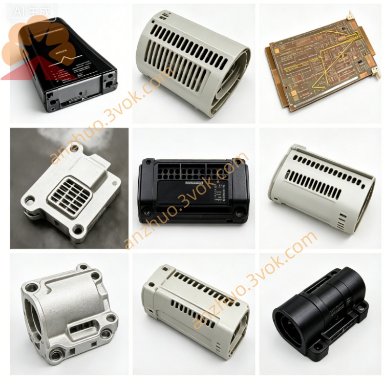
Emerson Ovation 5X00062G01 Hot-Swappable DCS I/O
The 5X00062G01 is a standard plug-in input/output module exclusively developed for the Emerson Ovation distributed control system. Serving as the key data exchange gateway between field measuring instruments, execution equipment and the central controller, it integrates comprehensive self-diagnosis functions and intuitive front panel LED status indicators for rapid fault location. Validated by strict anti-interference, vibration and temperature cycling aging tests and certified with CE and UL standards, the module supports flexible channel parameter configuration and non-stop hot swapping. It features full compatibility with original racks, backplanes and terminal bases, minimizing production downtime and delivering reliable long-term operation under severe industrial working conditions.
Description
3.1 Core Technical Parameters
Power supply is supplied by the DCS cabinet backplane bus. The permissible operating temperature range is 0 ℃ to +60 ℃, while the storage temperature spans -25 ℃ to +70 ℃. Relative humidity shall be maintained between 5% and 95% with no condensation occurring. Every signal channel adopts independent isolation design, accompanied by built-in surge suppression circuitry and short-circuit fuse protection for loop safety. The module adopts standard rack-mounted card structure and allows hot swapping during system online running. Its designed service life under rated working conditions is more than 10 years, conforming to CE EMC and LVD international safety specifications, and can be seamlessly assembled with all standard Ovation rack accessories and backplanes.
3.2 Installation & Wiring Instructions
Confirm the target rack slot is vacant and intact, with no bent or oxidized pins on the backplane golden fingers. Slide the module along the slot guide rails horizontally until the rear connector fully engages and locks with the backplane interface, then fasten the fixing screws on the front panel to avoid loosening caused by equipment vibration.Classify power terminals, signal input/output terminals and communication terminals strictly according to terminal base silk-screen markings. Select shielded twisted-pair cables with matched wire gauge for field wiring and crimp terminals firmly to avoid poor contact and signal drift. Separate high-power cables and weak signal cables during wiring layout to reduce crosstalk interference. A full continuity and insulation resistance test must be carried out before power-on commissioning to rule out short circuit, reversed polarity and misconnection issues.
3.3 Software Configuration Operation
Log into the Ovation engineering workstation with authorized engineer access and launch the configuration software. Create a new I/O point database, select model 5X00062G01 from the hardware library and bind the corresponding physical rack and slot address. Configure signal types, measurement ranges, alarm thresholds and logic attributes for each channel according to actual field instrument access requirements. Compile the configuration program completely and download it to the matched controller, execute online synchronization and verify signal acquisition precision. Conduct no-load test first followed by on-load joint debugging to confirm timely and accurate response of module output to upper control commands.
3.4 Indicator Light Explanation
The POWER LED keeps steady green for normal power supply; it turns off or lights red when slot power supply fails or the module internal power circuit is damaged.The COMM LED flashes green normally during controller communication; constant red light represents communication interruption, address mismatch or backplane bus failure.Each channel LED flashes green under normal signal transmission state; steady red light indicates open circuit, short circuit or fault of field connected devices.
3.5 Common Fault Handling
If the power indicator remains off after installation, check the slot power supply and fuse status, re-seat the module tightly and clean oxidized golden fingers if needed.Continuous red communication light requires verification of rack and slot address settings in configuration software and inspection of the rack main bus module operating status.Continuous channel fault alarms can be resolved by disconnecting field wiring and measuring loop resistance to locate open or short circuits and replacing defective field sensors or actuators.Severe signal fluctuation is generally triggered by unshielded wiring or nearby strong electromagnetic interference; replace standard shielded cables and install signal isolation components to stabilize signals.
3.6 Maintenance & Storage
Carry out routine maintenance every 3 months, shortened to once a month for heavily dusty working sites. Power off the cabinet before maintenance and remove dust and debris on the module and terminal base using dry compressed air. Check the tightness of fixing screws and wiring terminals quarterly and re-tighten loose connections. Export historical fault logs regularly to track long-term operating performance and predict potential hidden failures.Spare modules must be stored in original anti-static packaging inside a dry, ventilated constant-temperature warehouse to prevent extrusion, collision and static damage. Modules stored long-term need power-on activation and full-channel function testing every six months before field installation.
3.7 Application Fields
This I/O module is widely deployed in thermal power generation, petrochemical processing, metallurgy, municipal water supply and wastewater treatment, energy storage stations and other process industries. It undertakes analog and digital signal collection, interlock logic judgment and actuator driving control tasks in closed-loop production control loops, suitable for new DCS system construction, old control system upgrade and field equipment renovation projects.
Get a Quote