Emerson Ovation 5X00044G01 DCS I/O
The 5X00044G01 is a hot-swappable plug-in I/O module exclusively designed for Emerson Ovation distributed control system. It serves as the essential data interaction medium between field site measuring instruments, actuators and system controllers in process automation projects. Equipped with built-in comprehensive self-diagnosis circuits and front panel LED status indicators, it realizes real-time monitoring of power supply, bus communication and each signal channel operating status for rapid on-site fault positioning. This module undergoes strict anti-electromagnetic interference, vibration resistance and high-low temperature aging verification, and holds CE and UL international safety certifications. It supports flexible channel parameter configuration via the Ovation engineering workstation, features seamless compatibility with original racks, backplanes and matched terminal bases, and allows online replacement without cabinet power cut to reduce system downtime, delivering stable long-term operation under complex and harsh industrial working conditions.
Description
1. Single Sentence Title
Emerson Ovation 5X00044G01 DCS I/O Module Technical Specification, Product Introduction and Complete Operation User Manual
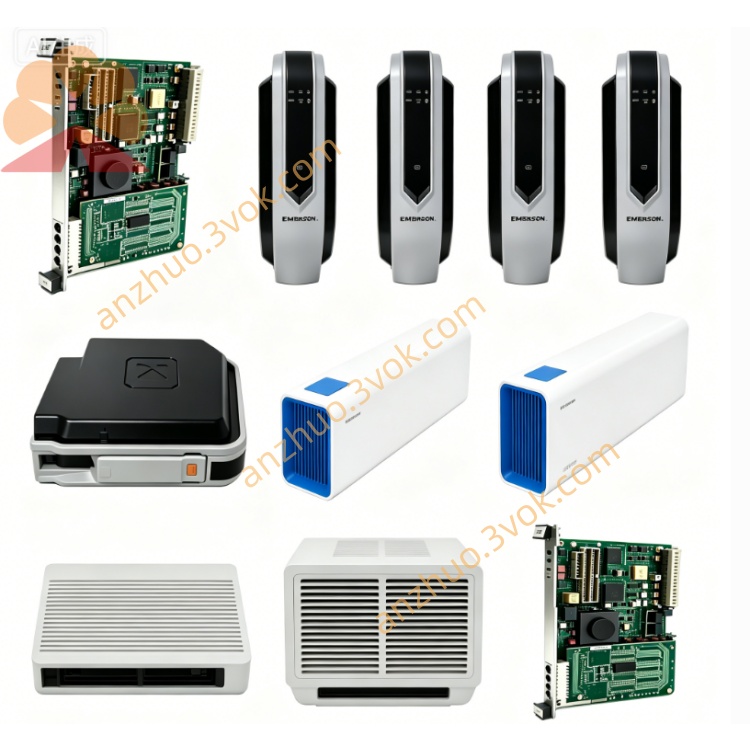
2. Product Brief Introduction
The 5X00044G01 is a hot-swappable plug-in I/O module exclusively designed for Emerson Ovation distributed control system. It serves as the essential data interaction medium between field site measuring instruments, actuators and system controllers in process automation projects. Equipped with built-in comprehensive self-diagnosis circuits and front panel LED status indicators, it realizes real-time monitoring of power supply, bus communication and each signal channel operating status for rapid on-site fault positioning. This module undergoes strict anti-electromagnetic interference, vibration resistance and high-low temperature aging verification, and holds CE and UL international safety certifications. It supports flexible channel parameter configuration via the Ovation engineering workstation, features seamless compatibility with original racks, backplanes and matched terminal bases, and allows online replacement without cabinet power cut to reduce system downtime, delivering stable long-term operation under complex and harsh industrial working conditions.
3. Technical Specifications
The module obtains working power supply directly from the cabinet backplane bus. Its operating ambient temperature ranges from 0℃ to +60℃, while the storage temperature covers -25℃ to +70℃. The applicable relative humidity is 5% to 95% without condensation. Each signal channel adopts independent isolation design, with built-in surge suppression and loop short-circuit fuse protection functions. It adopts standard rack card installation structure and supports hot swapping during operation. The theoretical service life under rated nominal working conditions exceeds 10 years, fully complying with CE EMC and LVD safety standards, and can be perfectly matched with all standard Ovation controller racks and backplane accessories.
4. User Manual
User Manual
Model No.: 5X00044G01Series: Emerson Ovation DCS I/O Module
Table of Contents
Safety Warnings
Installation Instructions
Wiring Operation Guidelines
Software Configuration Procedures
LED Indicator Description
Fault Diagnosis & Troubleshooting
Maintenance and Storage Requirements
Warranty Terms
1. Safety Warnings
Only certified professional automation engineers who have received systematic Ovation DCS technical training are allowed to carry out installation, wiring, commissioning and maintenance operations on this module.Cut off the power supply of the corresponding rack slot completely before plugging in or pulling out the module or modifying field wiring, so as to avoid electric shock accidents, hardware burnout or overall control system shutdown.Do not operate the module beyond the rated voltage, load and temperature range defined in specifications. Overload and out-of-range operation will cause irreversible hardware damage and invalidate the product warranty.The module must be installed inside a fully sealed control cabinet and kept away from flammable explosive gas, corrosive liquid, heavy dust accumulation, splashing water and strong electromagnetic interference sources including high-power inverters and contactors.Any unauthorized disassembly of the module shell, modification of internal circuits or replacement of non-original spare parts is prohibited, which will lead to the failure of product safety certification.Once abnormal overheating, peculiar smell, smoke or continuous fault alarms appear during running, cut off the power supply immediately, isolate the faulty module and contact the supplier’s technical support team for follow-up disposal.
2. Installation Instructions
Check that the target slot on the DCS rack is vacant and intact, and confirm the golden fingers of the backplane bus have no bending, oxidation, corrosion or attached foreign impurities.Align the guide rails on both sides of the module with the rack sliding grooves, push the module horizontally and smoothly inward until the rear connector is fully locked and tightly connected with the backplane bus interface.Tighten the fixing screws on the upper and lower positions of the front panel sequentially to prevent loosening and poor contact caused by long-term equipment vibration.Reserve sufficient heat dissipation space around the module, and do not stack cables, wire harnesses or other electronic components to block the ventilation gaps on the module housing.
3. Wiring Operation Guidelines
Distinguish power terminals, signal input channels, signal output channels and bus communication terminals strictly according to the screen printing marks on the matched terminal base.Select shielded twisted-pair cables with appropriate wire cross-section according to actual loop current, and crimp cable terminals firmly to eliminate poor contact and signal drift caused by loose wiring.Separate high-current power cables and weak signal cables during wiring layout to reduce mutual crosstalk interference. Bind scattered wire harnesses neatly with cable ties and fix them reliably to avoid pulling and abrasion during long-term equipment operation.Complete continuity test and insulation resistance inspection for all circuits after wiring construction, and confirm no short circuit, reversed polarity or misconnection exists before power-on trial operation.
4. Software Configuration Procedures
Log in to the Ovation engineering workstation with an authorized engineer account and open the dedicated configuration software.Create a new I/O point list, select module model 5X00044G01 from the hardware library, and bind the actual physical rack number and slot address.Set signal type, measurement range, alarm threshold and logic attributes independently for each channel according to the access demands of field instruments.Compile the complete configuration file and download it to the corresponding DCS controller, execute online data synchronization and verify the real-time signal collection accuracy of each channel.Conduct no-load power-on test firstly, then access actual loads for joint debugging, and verify that module output actions can respond accurately and timely to upper control commands.
5. LED Indicator Description
The POWER indicator keeps solid green under normal power supply status; it turns off or lights red when the slot power supply is abnormal or the module internal power circuit breaks down.The COMM indicator flashes green periodically during normal communication with the controller; constant red lighting indicates bus communication interruption, address setting mismatch or backplane bus failure.Each channel is equipped with an independent indicator light, which flashes green during normal signal transmission; constant red lighting represents channel loop open circuit, short circuit or breakdown of field connected equipment.
6. Fault Diagnosis & Troubleshooting
If the POWER indicator remains off after installation, check the power supply status and fuse condition of the corresponding rack slot, reinsert the module tightly, and clean the oxidized parts of backplane golden fingers when necessary.If the COMM indicator keeps glowing red, check whether the rack and slot address set in configuration software matches the actual physical installation position, and check the operating status of the rack main bus module simultaneously.When a single channel triggers persistent fault alarms, disconnect field wiring and measure loop resistance to check open circuit or short circuit faults, and replace damaged field sensors or actuators promptly.Sharp signal fluctuation is generally caused by unshielded wiring or nearby strong interference sources; replace standard shielded twisted-pair cables and install signal isolation components to suppress interference.
7. Maintenance and Storage Requirements
Implement routine maintenance every three months; shorten the maintenance cycle to one month for sites with severe dust and metal debris accumulation. Cut off the cabinet power supply in advance, and blow away dust and sundries on the module surface and terminal base with dry compressed air.Check the tightness of module fixing screws and wiring terminals every quarter, and re-tighten loose positions to avoid bad contact induced by long-term vibration.Export historical system fault logs regularly, record long-term operating conditions and alarm records of each channel, and conduct trend analysis to predict potential hidden troubles in advance.Unused spare modules shall be stored in original anti-static packaging bags and placed in a dry, ventilated constant-temperature warehouse, avoiding extrusion, collision and static damage from direct human touch. Long-term stored modules need power-on activation and full-channel function testing every six months before field installation and application.
8. Warranty Terms
This product enjoys standard limited warranty calculated from the delivery date, and the specific warranty period shall follow the formally signed purchase contract.Hardware damage caused by unauthorized disassembly, wrong wiring, overvoltage surge, man-made collision, water immersion and improper storage is not covered by free warranty service.For quality hardware failures within the warranty scope, the supplier provides free repair or replacement services; users shall bear the round-trip logistics costs generated by after-sales handling of non-quality faults.When applying for technical support, repair and replacement services, submit the complete part number, serial number and purchase contract number to the official after-sales department for verification and processing.
5. Application Fields
This module is widely applied in thermal power generation, petrochemical processing, metallurgy, water supply and wastewater treatment, energy storage and other large-scale process industries. It undertakes field analog and digital signal acquisition, interlock logic judgment and field actuator driving control tasks in production closed-loop control loops, and is applicable to new system construction, DCS system upgrading and old equipment reconstruction projects.
Get a Quote