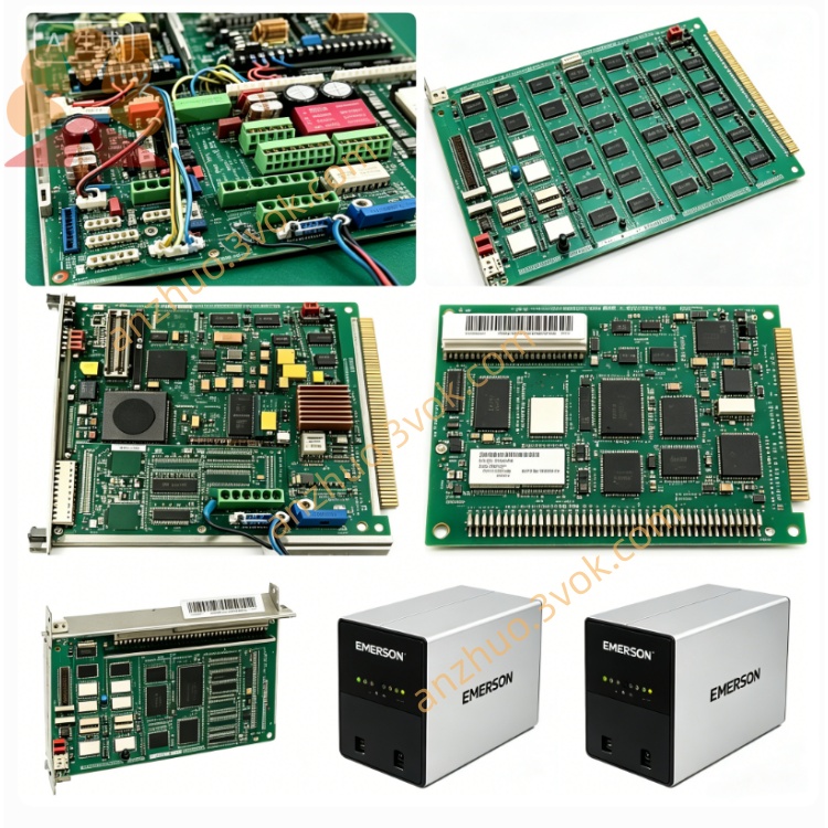
Emerson Ovation 5X00034G01 DCS I/O
Description
The module passes strict anti-electromagnetic interference, vibration resistance and high-low temperature aging tests and complies with CE and UL industrial safety standards, supporting long-term continuous operation in harsh industrial environments. It features hot-swap capability, allowing individual module replacement without shutting down the entire control cabinet to reduce unplanned equipment downtime. Each channel supports flexible parameter configuration through the Ovation engineering workstation, which is compatible with new construction and equipment renovation projects and boasts excellent versatility and scalability.
User Manual
Table of Contents
Safety Precautions
Product Overview & Technical Specifications
Mechanical Installation Guide
Wiring and Termination Instructions
Software Configuration Steps
LED Indicator Status Explanation
Fault Diagnosis and Troubleshooting
Maintenance, Storage and Warranty Provisions
Get a Quote