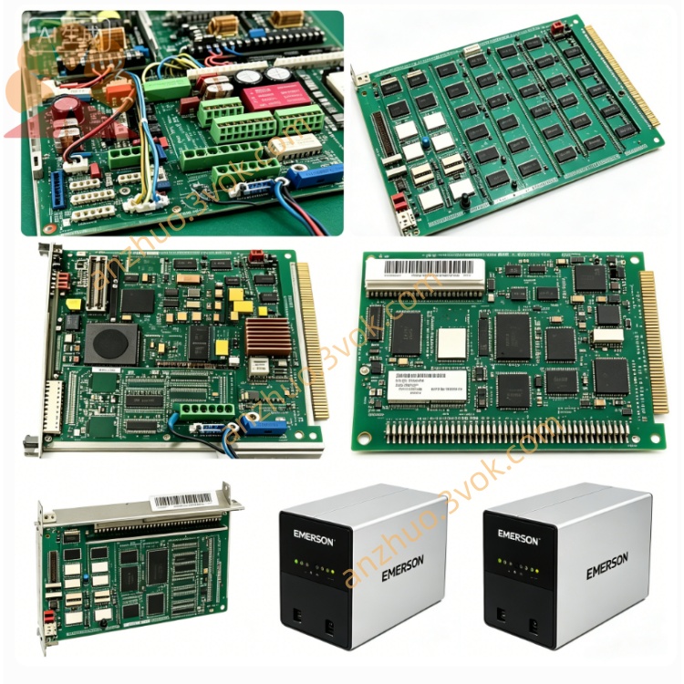
Emerson Ovation 5X00031H08 DCS Standard I/O Module
The 5X00031H08 is a plug-in input/output module exclusively designed for Emerson Ovation distributed control system. It serves as the signal interaction gateway between field site instruments, actuators and system controllers in thermal power, petrochemical and metallurgical process industries. Built-in comprehensive self-diagnosis circuits and front panel LED status lights enable quick fault location. With reliable anti-interference capability, wide working temperature range and hot-swap support, the module can be rapidly replaced without cabinet power cut, minimizing production downtime. Each channel supports flexible software parameter configuration via the Ovation engineering platform, and it is fully compatible with original racks, backplanes and terminal bases, delivering long-term stable operation under severe industrial field conditions with CE and UL safety certifications.
Description
The 5X00031H08 is a plug-in input/output module exclusively designed for Emerson Ovation distributed control system. It serves as the signal interaction gateway between field site instruments, actuators and system controllers in thermal power, petrochemical and metallurgical process industries. Built-in comprehensive self-diagnosis circuits and front panel LED status lights enable quick fault location. With reliable anti-interference capability, wide working temperature range and hot-swap support, the module can be rapidly replaced without cabinet power cut, minimizing production downtime. Each channel supports flexible software parameter configuration via the Ovation engineering platform, and it is fully compatible with original racks, backplanes and terminal bases, delivering long-term stable operation under severe industrial field conditions with CE and UL safety certifications.
3. User Manual (English, no tables)
User Manual
Model No.: 5X00031H08Series: Emerson Ovation DCS I/O Module
Contents
Safety Instructions
Product Overview & Technical Parameters
Installation Steps
Wiring Guidelines
Software Configuration Operations
LED Indicator Description
Fault Checking & Solutions
Maintenance, Storage and Warranty Terms
1. Safety Instructions
Only certified automation engineers with professional DCS training are allowed to install, wire, debug and maintain this module.Disconnect the power supply of the corresponding rack slot completely before plugging in or removing the module to avoid electric shock, hardware burnout or system outage.Do not apply the module beyond its rated voltage, load and temperature range. Overload operation will permanently damage hardware and void the warranty.Mount the module inside a sealed control cabinet, and keep it away from flammable gas, corrosive liquid, heavy dust, splashing water and strong electromagnetic interference sources.Unauthorized disassembly, internal circuit modification or replacement of non-original spare parts is prohibited and will invalidate product certifications.In case of abnormal heat generation, peculiar smell, smoke or persistent fault alarms during operation, cut off power immediately, isolate the faulty module and contact the supplier’s technical support team.
2. Product Overview & Technical Parameters
This module adopts integrated circuit structure and matched dedicated terminal base for field wiring. It collects on-site analog and digital signals and transmits control commands issued by the upper controller reliably.It takes power from the cabinet backplane bus directly. The working ambient temperature ranges from 0℃ to +60℃, storage temperature ranges from -25℃ to +70℃, and applicable relative humidity is 5%~95% non-condensing. It features channel isolation protection, surge suppression and short-circuit fuse protection, adopts standard rack plug-in mounting and supports hot swapping. The designed service life under rated working conditions is more than 10 years, complying with CE EMC and LVD international safety standards.
3. Installation Steps
Confirm the target rack slot is vacant and intact, and check that the backplane bus golden finger has no bending, oxidation or attached foreign matter.Align the module side guide rails with the rack chute, push the module horizontally and smoothly inward until the rear connector fully locks and connects tightly with the backplane interface.Tighten the fixing screws on the upper and lower parts of the front panel to prevent loosening and poor contact caused by long-term equipment vibration.Reserve enough surrounding space for heat dissipation, and do not stack cables or other components to block the ventilation gaps of the module housing.
4. Wiring Guidelines
Classify power terminals, signal input channels, signal output channels and communication terminals strictly according to the printing marks on the supporting terminal base.Select shielded twisted-pair cables with appropriate wire cross-section according to loop current, and crimp cable terminals firmly to avoid poor contact and signal drift.Separate high-power cables and weak signal cables during wiring layout to reduce crosstalk interference. Bind scattered wire harnesses neatly and fix them to prevent pulling and abrasion during long-term operation.Complete continuity test and insulation resistance inspection for all circuits after wiring, and confirm no short circuit, reversed polarity or misconnection before power-on test run.
5. Software Configuration Operations
Log in to the Ovation engineering workstation with an authorized engineer account and open the configuration software.Create a new I/O point list, select model 5X00031H08 from the hardware library, and bind the actual rack number and slot address.Set signal type, measurement range, alarm threshold and logic attributes independently for each channel according to field instrument access requirements.Compile the configuration file completely and download it to the matched controller, finish online synchronization and verify the signal acquisition accuracy of each channel.Carry out no-load power-on test first, then conduct joint debugging with actual loads, and verify that module output actions respond accurately to upper control commands.
6. LED Indicator Description
The POWER light keeps solid green under normal power supply; it turns off or glows red when the slot power supply is abnormal or the internal power circuit fails.The COMM light flashes green normally during controller communication; constant red light indicates communication interruption, address mismatch or backplane bus failure.Each channel has an independent indicator light that flashes green during normal signal transmission; constant red light means channel open circuit, short circuit or on-site equipment failure.
7. Fault Checking & Solutions
If the POWER light stays off after installation, check the slot power supply status and fuse condition, reinsert the module tightly and clean the oxidized golden fingers of the backplane if needed.If the COMM light remains red continuously, verify whether the rack and slot address set in configuration software matches the physical installation position, and inspect the operating state of the rack main bus module simultaneously.For continuous fault alarms on a single channel, disconnect field wiring and measure loop resistance to check open or short circuit faults, and replace damaged field sensors or actuators timely.Severe signal fluctuation usually results from unshielded wiring or nearby strong interference sources; replace standard shielded twisted-pair cables and install signal isolation components to suppress interference.
8. Maintenance, Storage and Warranty Terms
Carry out routine maintenance every three months; shorten the cycle to one month for heavily dusty sites. Cut off cabinet power first and blow away dust and debris on the module and terminal base with dry compressed air.Check the tightness of fixing screws and wiring terminals quarterly and re-tighten loose positions to avoid bad contact caused by long-term vibration.Export system fault logs regularly and record channel operation status and alarm data for potential fault prediction.Unused spare modules shall be stored in original anti-static packaging inside a dry, ventilated constant-temperature warehouse to avoid extrusion, collision and static damage. Long-term stocked modules need power-on activation and full-channel function testing every six months before field installation.The product enjoys standard limited warranty starting from the delivery date, with the specific warranty period subject to the signed purchase contract. Damage caused by unauthorized disassembly, wrong wiring, overvoltage shock, artificial collision and improper storage is excluded from free warranty coverage. Free repair or replacement is provided for quality failures within the warranty scope, while the user shall bear round-trip logistics costs for non-quality related after-sales services. Submit the complete part number, serial number and purchase contract number to official after-sales department for technical support and after-sales processing.
Get a Quote