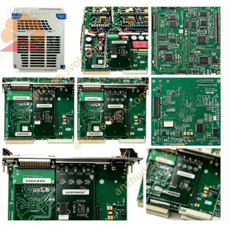
Emerson Ovation 5X00006H12 DCS I/O Module
The 5X00006H12 is a standard plug-in I/O module exclusively designed for Emerson Ovation distributed control system, serving as the signal interaction bridge between field site instruments, actuators and central controllers in process industrial automatic control systems.
Description
This module adopts integrated modular hardware architecture, consisting of electronic main board, signal adaptation personality module and matched terminal base, featuring compact structure and standard rack installation layout. It realizes stable collection of on-site analog and digital signals as well as reliable transmission of control commands issued by the upper controller, and is fully compatible with the whole Ovation system bus architecture without extra hardware transformationEmerson.
Built-in comprehensive multi-level self-diagnosis logic covers power supply detection, bus communication status monitoring, channel open-circuit and short-circuit inspection and loop grounding fault judgment. Front-panel LED indicator lights directly display real-time operating status, which greatly shortens on-site fault location time for maintenance personnel. It passes strict anti-electromagnetic interference, vibration resistance and high-low temperature aging verification, and has obtained CE and UL industrial safety certifications, capable of long-term continuous stable operation in harsh industrial environments such as thermal power plants, petrochemical plants and metallurgical workshops.
The module supports hot swapping without shutting down the whole cabinet system during replacement, which effectively avoids unplanned system downtime and production interruption. Each signal channel supports flexible software parameter configuration through Ovation dedicated engineering workstation, adapting to various types of field sensors and execution equipment, with strong universality and expansibility for project reconstruction and new construction projectsEmerson.
3. Complete English User Manual (No Tables)
User Manual
Model: 5X00006H12Brand: Emerson Ovation DCS Series
Table of Contents
Safety Warnings & Precautions
Product Overview & Technical Specifications
Mechanical Installation Operation Guide
Wiring & Termination Operation Guidelines
System Software Configuration Steps
LED Indicator Operating Status Explanation
Fault Diagnosis & Troubleshooting Instructions
Routine Maintenance, Storage Rules & Warranty Terms
1. Safety Warnings & Precautions
Only professional automation engineers who have received systematic training on Ovation DCS system are allowed to carry out installation, wiring, commissioning and maintenance operations for this module.Before plugging in or pulling out the module, modifying field wiring or overhauling terminals, completely cut off the power supply of the corresponding cabinet slot to prevent electric shock accidents, hardware burnout or overall control system outage.Do not operate the module beyond the rated voltage, signal load and ambient temperature range marked in the technical specifications. Overload and out-of-range operation will cause permanent hardware damage and invalidate the product warranty service.The module must be installed inside a sealed control cabinet. Keep it far away from flammable and explosive gas, corrosive liquid, thick dust accumulation, direct water splashing and strong electromagnetic radiation sources such as large frequency converters and high-power contactors.It is forbidden to disassemble the module shell, cut internal circuits or replace non-original spare parts without official authorization from Emerson. Unauthorized modification will lead to loss of equipment safety certification.If abnormal heating, peculiar smell, smoke or continuous fault alarms occur during running, cut off the power supply immediately, isolate the faulty module and contact the supplier’s technical support team for follow-up processing.
2. Product Overview & Technical Specifications
2.1 Product Overview
The 5X00006H12 belongs to the standard series I/O card of Ovation DCS system. It completes two core tasks: converting analog and digital signals collected from on-site field devices into bus data and uploading them to the controller, and converting the control instructions sent down by the controller into actual driving signals to control field actuators. It is a key link for closed-loop automatic control of production processes.
2.2 Key Technical Parameters
Rated working power supply adopts standard cabinet backplane bus power supply mode; working ambient temperature ranges from 0 ℃ to +60 ℃, and storage temperature ranges from -25 ℃ to +70 ℃. The applicable relative humidity is 5%~95% without condensation. Channel insulation strength reaches industrial standard 1000V isolation level, with built-in surge suppression and loop short-circuit fuse protection functions. The module supports standard rack plug-in installation and hot swapping, and the designed service life under rated working conditions is no less than 10 years. It complies with CE EMC and LVD safety standards and can be matched with all standard Ovation controller racks and backplanes.
3. Mechanical Installation Operation Guide
Check whether the target slot on the DCS cabinet rack is vacant and intact in advance, and confirm that the backplane bus golden finger has no bending, oxidation, corrosion or foreign matter adhesion.Align the guide rails on both sides of the module with the chute of the rack slot, push the module steadily and horizontally inward until the rear connector is fully locked and tightly connected with the backplane bus interface.Tighten the fixing screws on the upper and lower sides of the module front panel in turn to prevent the module from loosening and poor contact caused by long-term equipment vibration during operation.Reserve enough ventilation space around the module to ensure natural heat dissipation; do not stack cables, wire bundles or other electronic components to block the heat dissipation gap of the module shell.
4. Wiring & Termination Operation Guidelines
Distinguish power terminals, signal input channels, signal output channels and bus communication terminals strictly according to the silk-screen marking on the matched terminal base of the module.Select shielded twisted-pair cables with appropriate wire cross-section for on-site signal wiring according to the rated loop current. Crimp cable terminals firmly to avoid virtual connection, signal drift and unstable data collection caused by loose wiring.Separate strong-current power cables and weak-current signal cables in wiring routing to eliminate mutual crosstalk interference. Bind scattered wire harnesses neatly with cable ties and fix them to avoid pulling and abrasion during long-term equipment operation.After wiring is finished, conduct full-circuit continuity test and insulation resistance inspection one by one, confirm there is no short circuit, reversed polarity or misconnection of any channel, and then carry out power-on trial operation.
5. System Software Configuration Steps
Log in to the Ovation system engineering workstation with an authorized engineer account and open the system configuration software.Create a new I/O point list, select the module model 5X00006H12 in the hardware library, and bind the physical rack number and slot address corresponding to the actual installation position.Set independent parameters for each channel in sequence, including signal type definition, measuring range calibration, alarm threshold setting and logic attribute assignment according to on-site instrument access requirements.Compile the edited configuration file completely and download it to the corresponding DCS controller, execute online data synchronization, and verify the accuracy of real-time signal uploading of each channel.Carry out no-load power-on test first, then access the actual load for joint debugging, and confirm that the output action of the module can respond accurately and timely to the control instructions issued by the upper system.
6. LED Indicator Operating Status Explanation
The POWER indicator light keeps solid green under normal power supply state; if the light goes out or turns red, it indicates abnormal power access of the slot or internal power circuit failure of the module itself.The COMM indicator flashes green periodically when communicating normally with the controller; constant red lighting means bus communication interruption, address mismatch or backplane bus failure.Each channel corresponds to an independent channel indicator light, which flashes green normally during signal transmission; constant red lighting represents channel loop open circuit, short circuit or field equipment failure.
7. Fault Diagnosis & Troubleshooting Instructions
If the POWER indicator is off after installation, check whether the corresponding rack slot is powered normally and whether the slot fuse is blown. Pull out the module slightly and reinsert it firmly, and clean the oxidized parts of the backplane bus golden finger if necessary.If the COMM indicator keeps red permanently, recheck whether the rack and slot address set in the system configuration software is consistent with the actual physical installation position, and inspect the working state of the rack main bus module at the same time.If a single channel triggers a continuous fault alarm, disconnect the field wiring and measure the loop resistance to judge whether there is open circuit or short circuit on the site side, and replace the damaged field sensor or actuator in time.If the collected signal value fluctuates violently and cannot stabilize for a long time, check whether unshielded cables are used for wiring and whether strong electromagnetic interference sources are arranged nearby. Replace standard shielded twisted-pair cables and add signal isolation components to suppress interference.
8. Routine Maintenance, Storage Rules & Warranty Terms
8.1 Routine Maintenance
Carry out regular maintenance once every three months; for sites with serious dust and metal debris accumulation, shorten the maintenance cycle to one month. Cut off the cabinet power supply first, and use dry compressed air to blow away dust and debris on the module surface and terminal base.Check the tightness of module fixing screws and wiring terminals quarterly, and re-tighten any loose parts to prevent poor contact caused by long-term vibration.Export system historical fault logs regularly, record the long-term operating state and abnormal alarm records of each channel, and conduct trend analysis to predict potential hidden troubles in advance.
8.2 Storage Rules
Spare unused modules shall be kept in the original anti-static packaging bag, placed in a dry, ventilated and constant-temperature warehouse, and avoid extrusion, collision and static electricity damage caused by direct contact with human bodies.Modules stored for a long time shall be taken out for power-on activation and full-channel function test every six months before being put into on-site installation and use again.
8.3 Warranty Terms
The product enjoys a standard limited warranty period calculated from the delivery date, and the specific warranty time limit shall be subject to the formal signed purchase contract.Hardware damage caused by unauthorized disassembly, wrong wiring, overvoltage impact, artificial collision, water immersion and improper storage is not covered by free warranty service.For hardware quality faults occurring within the warranty scope, the supplier provides free repair or replacement services; users need to bear the round-trip logistics costs generated by non-quality failure after-sales processing.When applying for technical support and after-sales replacement and repair services, provide the complete module part number, serial number and purchase contract number to the official after-sales department for verification and processing.
Get a Quote