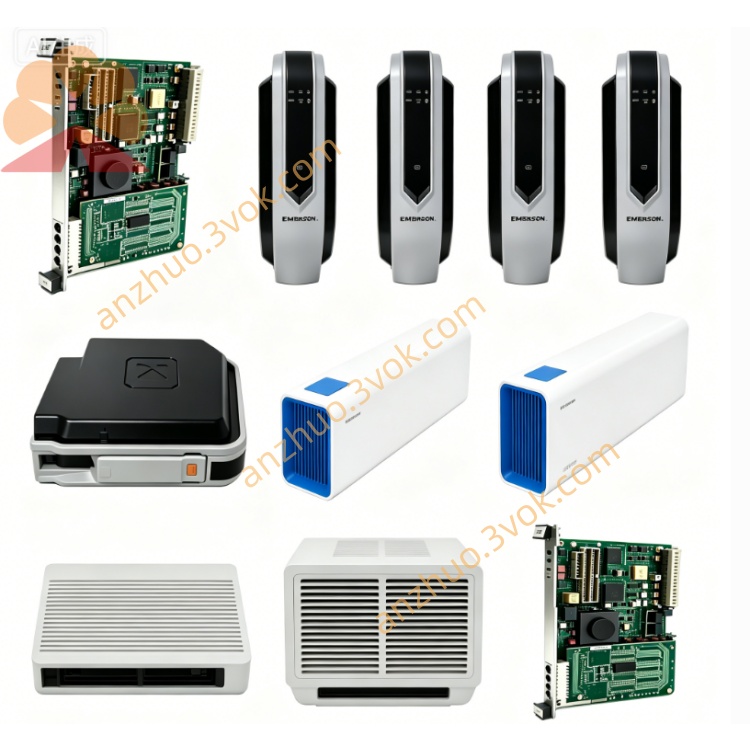
Emerson Ovation 5X00001H15 DCS Input/Output Module
Description
Core Features
- Strong System CompatibilityPerfectly matched with Emerson Ovation DCS platform, also compatible with mainstream PLC and industrial control systems; supports seamless system upgrade and smooth migration from legacy WDPF system to Ovation architecture, realizing fast substation-level I/O reconstruction and shortening project transformation cycle.
- Flexible Software ConfigurationEach signal channel supports multi-type parameter setup including RTD sensor mode, signal range definition and logic assignment via dedicated configuration software, meeting diversified on-site signal access requirements.
- Comprehensive Self-Diagnosis FunctionBuilt-in multi-dimensional fault detection mechanisms: communication timeout monitoring, fuse state detection, ground fault diagnosis, etc. Equipped with onboard LED indicator lights to real-time display power supply status, controller communication link and internal/external module faults, facilitating rapid troubleshooting.
- High Industrial ReliabilityPasses strict factory aging test, vibration and anti-electromagnetic interference verification; certified with CE and UL international safety standards, stable for long-term continuous operation under harsh industrial environments. Compact plug-in design enables hot swapping and quick on-site replacement, minimizing equipment downtime.
Typical Application Scenarios
3. Complete English User Manual(英文版完整说明书)
User Manual
Table of Contents
Safety Warnings & Precautions
Product Overview & Technical Specifications
Mechanical Installation Guide
Wiring Definition & Termination Instructions
Software Configuration Steps
Indicator Light Status Description
Fault Diagnosis & Troubleshooting
Maintenance, Storage & Warranty
1. Safety Warnings & Precautions
Only certified industrial automation engineers with DCS system operation training are allowed to install, wire, debug and maintain this module.
Cut off the cabinet internal power supply completely before plugging/unplugging the module or modifying field wiring to avoid electric shock, module burnout or system outage.
Do not exceed the rated voltage, signal load and temperature range specified in technical parameters; overload operation will permanently damage hardware and void warranty service.
Install the module inside sealed control cabinet; keep away from flammable gas, corrosive liquid, heavy dust, water splashing and strong electromagnetic radiation sources.
It is prohibited to disassemble the module housing, modify internal circuits or replace non-official spare parts without Emerson authorized approval.
Immediately cut off power and isolate the faulty module if abnormal heating, smoke, peculiar smell or constant fault alarm occurs during operation; contact supplier technical support.
2. Product Overview & Technical Specifications
2.1 Overview
2.2 Key Technical Parameters
Rated Operating Voltage: 220V AC
Output Frequency: 50kHz
Protection Class: Industrial grade anti-surge & anti-EMI
Certification: CE, UL
Installation Mode: Standard rack plug-in mounting
Operating Ambient Temperature: 0℃ ~ +60℃
Storage Temperature: -25℃ ~ +70℃
Relative Humidity: 5%~95% non-condensing
Service Life: ≥10 years under standard working conditions
3. Mechanical Installation Guide
Confirm the DCS cabinet rack slot is vacant and the backplane bus interface is intact without pin bending or oxidation.
Align the module guide rail with the rack slot, push the module steadily inward until it locks tightly with the backplane bus connector.
Tighten the fixing screws on both sides of the module front panel to prevent loosening caused by equipment vibration.
Reserve sufficient space around the module for heat dissipation; avoid stacking cables or other components blocking ventilation openings.
4. Wiring Definition & Termination Instructions
Distinguish power terminals, analog input channels, digital input/output channels and communication terminals strictly according to the terminal label printed on the module terminal base.
Select matched cross-section shielded signal cables for field wiring; crimp cable terminals firmly to avoid virtual connection and signal drift.
Separate strong power cables and weak signal cables in wiring routing to eliminate crosstalk interference. Bind cables neatly with cable ties and fix wiring harnesses to prevent pulling during equipment operation.
Complete full circuit continuity test and insulation resistance test before power-on; confirm no short circuit or reversed polarity wiring.
5. Software Configuration Steps
Open Emerson Ovation system configuration workstation and log in with authorized engineer account.
Create a new I/O point list, select model 5X00001H15 and bind the physical rack & slot address.
Configure each channel individually: set signal type (RTD/4-20mA/DI/DO), measuring range, alarm threshold and logic attributes.
Download the compiled configuration data to the DCS controller, perform online synchronization and verify channel signal collection accuracy.
Execute no-load test and full-load joint debugging sequentially; confirm control output actions respond correctly to system commands.
6. Indicator Light Status Description
| LED Indicator | Normal Status | Fault Status | Explanation |
|---|---|---|---|
| POWER | Solid Green | Off / Red | Normal power supply / Power loss or internal power circuit failure |
| COMM | Flashing Green | Solid Red | Normal communication with controller / Bus communication interruption |
| CHx | Flashing Green | Solid Red | Channel normal signal transmission / Channel open circuit/short circuit fault |
7. Fault Diagnosis & Troubleshooting Table
| Fault Phenomenon | Possible Root Causes | Resolution Methods |
|---|---|---|
| POWER light off after installation | Cabinet slot no power supply, backplane contact poor | Check rack power fuse; re-seat module and clean bus pins |
| COMM light keeps red | Configuration address mismatch, backplane bus fault | Recheck slot address setting; inspect DCS controller bus module |
| Single channel constant fault alarm | Field wire open/short, sensor damage | Test on-site loop resistance; replace faulty field sensor |
| Signal value severe fluctuation | Unshielded wiring, strong interference | Replace shielded twisted-pair cable; add signal isolation barrier |
8. Maintenance, Storage & Warranty
8.1 Routine Maintenance
Every 3 months (or monthly for high-dust sites), power off the cabinet and clean module surface dust and metal debris with dry compressed air.
Quarterly check module fixing screws and terminal wiring terminals for looseness; re-tighten promptly if loose.
Export system fault logs regularly, record channel operation status and abnormal alarm records for trend analysis.
8.2 Storage Requirements
Spare modules shall be stored in original anti-static packaging, placed in dry, ventilated constant temperature warehouse, avoiding extrusion, collision and static electricity damage.
Long-term stored spare parts shall be taken out for power-on activation test every 6 months before on-site deployment.
8.3 Warranty Statement
Standard 12-month limited warranty valid from delivery date; detailed warranty terms refer to formal purchase contract.
Damage caused by unauthorized disassembly, wrong wiring, overvoltage impact, man-made collision and improper storage is excluded from free warranty coverage.
For hardware quality failures within warranty scope, supplier provides free repair or replacement; users bear round-trip logistics costs for non-quality faults.
Provide module part number, serial number and purchase contract number to official after-sales department for technical support and after-sales processing.
Get a Quote