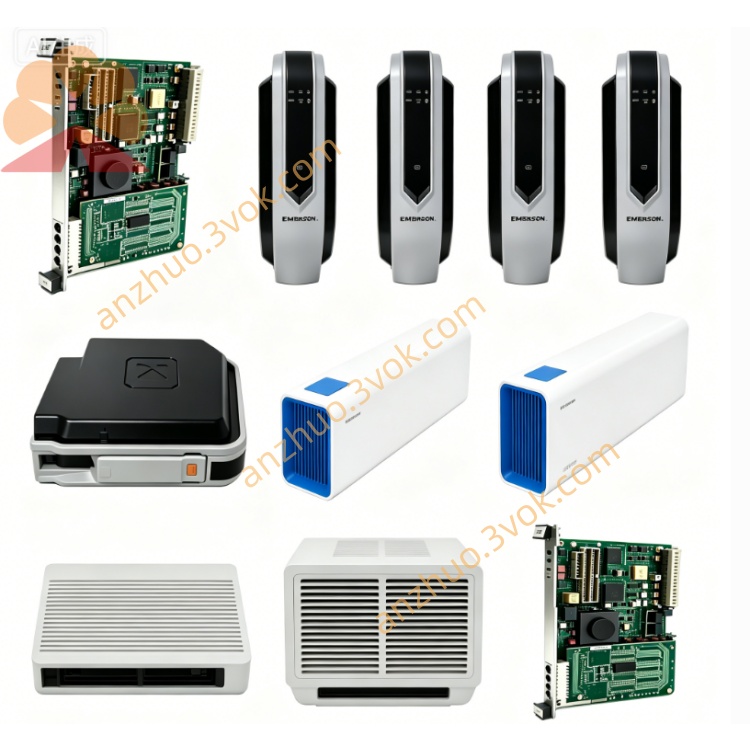
Emerson 5D92848G01 Ovation DCS System Control Module
Description
Table of Contents
Safety Precautions
Product Overview & Technical Parameters
Installation Steps
Wiring & Connection Instructions
Operation Guide
Troubleshooting & Fault Diagnosis
Maintenance & Storage Requirements
Warranty Statement
1. Safety Precautions
Only professional technicians who have received relevant electrical and mechanical training are allowed to install, wire and maintain this product.
Cut off the total power supply completely before any wiring, disassembly or overhaul work to avoid electric shock or equipment burnout accidents.
Do not use the product beyond the rated voltage, load and working range specified in the parameters; overload operation will cause permanent damage and invalidate the warranty.
Keep the product away from flammable, explosive, corrosive gas, liquid and heavy dust environments; avoid direct rainwater splashing and long-term high humidity immersion.
Do not arbitrarily modify the internal circuit structure, cut off built-in lines or replace non-original spare parts without official authorization.
When abnormal heating, peculiar smell, smoke or abnormal noise occurs during operation, cut off power immediately and stop using it, and contact the supplier for after-sales support.
2. Product Overview & Technical Parameters
2.1 Overview
2.2 Key Technical Parameters (Reserved for filling actual data)
Rated Operating Voltage:
Rated Operating Current:
Operating Temperature Range:
Protection Grade:
Installation Dimension:
Weight:
Service Life:
3. Installation Steps
Confirm the installation position meets space size, heat dissipation and vibration avoidance requirements, and fix the mounting bracket firmly on the equipment base.
Align the product mounting holes with the reserved fixing holes, use standard matching bolts for locking, and control the tightening torque within the specified range to avoid shell deformation.
Check that the product is fixed without shaking, tilting or loose fitting; reserve sufficient space around for heat dissipation and later disassembly inspection.
4. Wiring & Connection Instructions
Distinguish power terminals, signal input terminals and output execution terminals strictly according to the terminal definition label on the product housing.
Select wires with matching wire gauge according to rated current, and conduct crimping or terminal pressing treatment at wire joints to prevent loose contact and virtual connection.
Complete wiring in sequence, bind and fix scattered wires with cable ties to avoid pulling and abrasion during equipment operation.
Double-check all wiring circuits for short circuit, reversed polarity and misconnection; conduct insulation test before power-on trial run.
5. Operation Guide
After confirming installation and wiring are correct, close the equipment cabinet door and restore the power supply circuit.
Carry out no-load power-on test first, observe the indicator light status of the product, and confirm no abnormal alarm or abnormal heating.
Gradually access the rated load for simulated operation, verify signal transmission and action execution are accurate and consistent with design requirements.
Formal continuous operation can be started after 30 minutes of stable trial operation without abnormalities.
6. Troubleshooting & Fault Diagnosis
| Fault Phenomenon | Possible Causes | Solutions |
|---|---|---|
| No response after power-on | Power supply disconnection, reversed wiring polarity, fuse blown | Recheck power circuit, correct wiring, replace matched fuse |
| Indicator flashes abnormally | Signal line loose contact, peripheral host communication failure | Reconnect signal terminals, check host communication parameters |
| Excessive temperature rise under normal load | Poor heat dissipation, long-term overload operation | Clean dust around heat dissipation area, reduce actual load to rated range |
| Execution action lag / inaccurate | Parameter setting error, terminal virtual connection | Reset control parameters, re-crimp loose wiring terminals |
7. Maintenance & Storage Requirements
7.1 Daily Maintenance
Regularly power off and clean surface dust, metal scraps and attachments every 1–3 months according to the on-site environment.
Periodically check whether fixing bolts and wiring terminals are loose, and re-tighten them timely if any looseness is found.
Record operation status, working load and running duration for routine inspection and tracking.
7.2 Storage
Store the unused product in a dry, ventilated and room-temperature warehouse, with packaging intact, avoiding extrusion and collision.
Storage ambient humidity shall be controlled within the standard range, and avoid long-term stacking in low-temperature frosting or high-humidity mildew environments.
Long-term stored products shall be subjected to power-on activation inspection every 6 months before reuse.
8. Warranty Statement
The product enjoys standard limited warranty from the date of delivery; the specific warranty period shall refer to the delivery contract.
Damage caused by unauthorized disassembly, wiring error, overload use, natural disaster, man-made collision and improper storage is not covered by free warranty service.
For quality problems within the warranty scope, the supplier provides free repair or replacement support; users shall bear the round-trip logistics cost for non-quality faults.
Contact the official after-sales department with the product serial number and purchase voucher for technical support and return & exchange services.
Get a Quote