Fanuc A06B-6071-K203 Servo Amplifier Connector Kit A63L-0001 Series Plug CNC Spare
Description
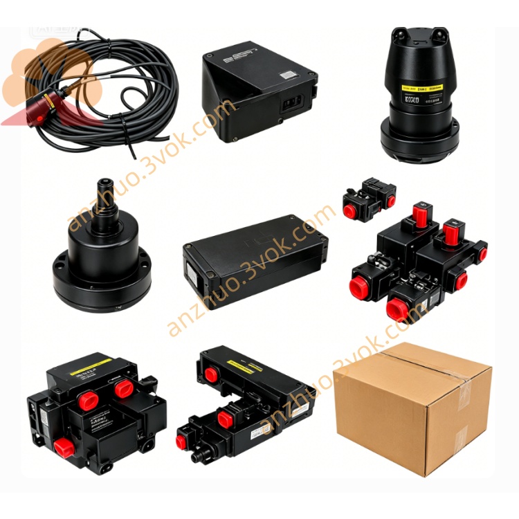
FANUC A06B-6071-K203 Connector Kit
1.
2. Product Features
Type: Connector kit (power/signal interface)
Compatible Modules: FANUC PSM power supply modules, α series servo amplifiers (A06B-6071 series)
Connector Types: CX1A, CX3, CX4 connectors (matching A63L-0001-0456, A63L-0001-0460/3HKX/3HKY)
Material: High-temperature resistant plastic housing, gold-plated contact pins for conductivity and corrosion resistance
Design: Tapered shaft (TPR) and keyed shaft (Key) design for secure, precise fitting
Protection: IP20 rating, suitable for internal electrical cabinet use
Weight: Approx. 0.05 kg (0.11 lbs)
Status: Discontinued by FANUC; available as new old stock or original surplus
RoHS Compliance: Meets EU environmental standards
3. Application Scope
Equipment: FANUC CNC systems (Series 16i, 18i, 21i, α series), PSM power supply units, servo amplifiers, and I/O modules
Machines: CNC lathes, machining centers, milling machines, and automation production lines
Functions: Power connection for PSM to servo amplifiers, signal transmission for control and feedback circuits, system wiring and maintenance replacement
4. Kit Components
Connector housings (CX1A, CX3, CX4 types)
Male/female contact pins (pre-crimped)
Locking clips and mounting hardware
Cable strain relief accessories
Installation instructions (basic wiring guide)
5. Installation Instructions
Power Off: Disconnect all system power before installation to avoid electric shock or component damage.
Connector Preparation: Strip cable insulation to the specified length; crimp pins to conductors using a FANUC-certified crimp tool.
Pin Insertion: Insert crimped pins into the connector housing according to the official FANUC pinout diagram; ensure pins click into place securely.
Cable Routing: Route cables with proper strain relief; avoid sharp bends or tension to prevent pin detachment or insulation damage.
Mating Connectors: Align connectors by key orientation; push firmly until the locking clip engages to ensure a secure connection.
Inspection: Verify all pins are fully seated, connections are tight, and no exposed conductors exist before restoring power.
6. Wiring Requirements
Cable Specifications: Use FANUC-specified power/signal cables with matching gauge (AWG) for the connector pins.
Pin Assignment: Strictly follow FANUC’s official wiring diagram; do not swap pin positions or modify connections.
Shielding: For signal cables, connect shields to the designated ground pin or chassis ground to reduce electromagnetic interference.
Torque: Tighten connector mounting screws to the recommended torque (0.5–0.8 N·m) to avoid over-tightening or loosening.
7. Working Environment
Operating Temperature: -10°C to +60°C
Storage Temperature: -20°C to +70°C
Relative Humidity: ≤85% (non-condensing)
Environment: Avoid corrosive gases, oil mist, conductive dust, and direct sunlight; keep the electrical cabinet clean and dry.
8. Maintenance Instructions
Periodic Inspection: Every 3 months (power off), check connectors for looseness, corrosion, or pin bending; clean dust from connector surfaces with a dry soft cloth.
Replacement: Replace the connector kit immediately if pins are damaged, housings are cracked, or connections become unstable.
Prohibition of Modification: Do not modify connector pins or housings; use only original FANUC replacement parts to ensure compatibility and safety.
9. Safety Precautions
Qualified Personnel: Installation, wiring, and maintenance must be performed by qualified electrical technicians with knowledge of FANUC CNC systems.
No Hot Plugging: Never connect or disconnect connectors with power on; this may cause arcing, damage components, or result in electric shock.
Secure Connections: Ensure all connectors are fully locked and cables are properly routed to prevent accidental disconnection during operation.
Overload Prevention: Do not exceed the connector’s rated current to avoid overheating, melting, or fire hazards.
Get a Quote