Detailed Product Description of B&R 7DI140.70 Digital Input Module
1. Product Overview
7DI140.70 is a slave-type digital input expansion module entirely manufactured in Austria for the B&R System 2003 PCC modular industrial control platform. Its core function is to collect 24VDC discrete switching signals from field automation equipment, including limit switches, proximity sensors, photoelectric detectors, safety gate interlock contacts, auxiliary feedback switches and emergency stop components. The module transmits real-time channel status data and built-in diagnostic fault codes to 7CP series master CPUs through the exclusive differential backplane bus of System 2003. As a pure slave expansion unit, it has no independent logic operation, motion calculation or program running capability; all signal judgment, interlock control and data processing are executed completely by the upper master CPU. B&R has fully discontinued the production of the entire System 2003 hardware line. Available supply includes brand-new original imported surplus units and fully inspected refurbished spare modules for maintenance, equipment transformation and emergency replacement of aging automated production lines. The module has passed CE and UL/cULus global industrial safety certification, with built-in optimized EMC filter circuits to suppress electromagnetic interference generated by servo drives, frequency inverters and contactor switching noise inside compact control cabinets. Genuine imported products are equipped with factory inspection test reports, Austrian certificates of origin and complete import customs clearance documents.
2. Mechanical Structure and DIN Rail Backplane Installation
This digital input module adopts the unified plug-in mechanical size standard of System 2003 hardware, achieving full mechanical compatibility with all 7BP DIN rail backplane models, such as 7BP701.1, 7BP702.0, 7BP703.0, 7BP704.0, 7BP707.0, 7BP708.0 and 7BP709.0. It belongs to slave expansion equipment and can only be installed in idle slave slots behind the first dedicated master CPU slot of any 7BP backplane. Installing it into the master CPU slot will directly cause backplane bus initialization failure and continuous fault alarm state.
An integrated elastic snap lock is formed at the bottom of the casing for quick and stable fixing on standard 35mm DIN rails. Push the module horizontally and fully insert it until the front panel is completely flush with the backplane surface, then press down the snap lock to lock firmly without extra auxiliary fixing brackets and fasteners. The outer shell is injection molded with flame-retardant reinforced industrial plastic in accordance with strict Austrian production standards, possessing excellent impact resistance and long-term anti-aging performance for long-time sealed cabinet operation. The protection grade is IP20, which only allows installation in closed indoor electrical cabinets; exposure to open air, liquid splashes, oil mist and heavy dust environments is strictly forbidden.
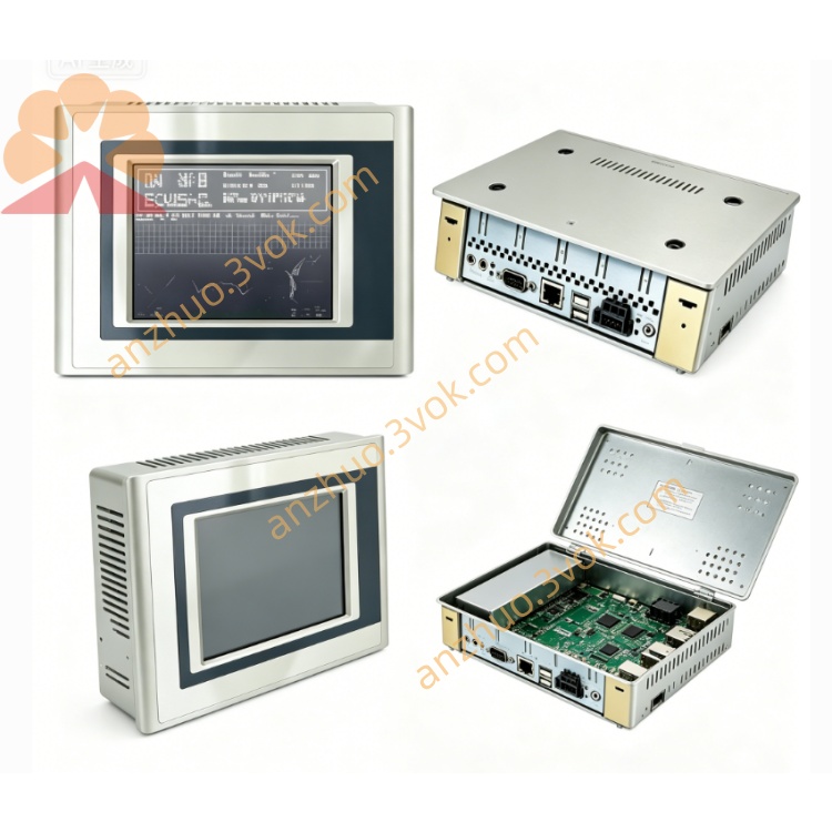
Multiple multi-color LED status indicators are neatly arranged on the front panel to provide real-time visual feedback, including module power supply state, backplane bus communication link quality, activation state of each independent digital input channel and overall module fault alarm signal, supporting fast on-site channel troubleshooting without external testing instruments. Permanent high-precision laser marking is printed on the casing, showing B&R brand logo, complete part number 7DI140.70, hardware revision code, unique factory serial number, production batch code and obvious "Made in Austria" origin mark, realizing full end-to-end supply chain traceability and genuine product authentication. The mechanical assembly meets EN 60068-2-6 vibration and shock resistance standards verified by Austrian factory tests, and can run stably under continuous low-frequency vibration generated by servo spindles, conveyor lines and automated processing machinery for long production cycles.
3. Electrical Specifications and Power Supply Performance
Backplane Logic Power Supply
The internal control logic power of the module is rated 24VDC, evenly supplied by the internal power bus integrated on the 7BP backplane, with an allowable voltage fluctuation range of 18VDC to 30VDC. The power consumption is low and stable under normal working conditions, and will not bring excessive load pressure to the special 24VDC rack power supply units of System 2003. The module is not equipped with an onboard backup battery; the system clock timing and overall task scheduling of the whole rack are centrally managed by the installed 7CP series master CPU.
Field Digital Input Circuit Parameters
The nominal field signal voltage supported by the module is 24VDC, and it provides universal wiring compatibility for both NPN sinking and PNP sourcing sensors. Every independent digital input channel is equipped with special hardware protection circuits to prevent overvoltage, reverse polarity connection, open circuit and short circuit faults. Configurable digital signal filtering hardware is embedded in each channel, and the filtering time can be adjusted through parameter settings in B&R Automation Studio software to eliminate contact bounce interference and electromagnetic noise induced by long-distance field wiring.
Complete galvanic isolation is designed between the internal backplane control circuit and the external field input circuit, which effectively eliminates ground loop potential difference interference frequently encountered in multi-servo densely arranged cabinet environments. Multi-layer built-in protection circuits realize overvoltage suppression, overcurrent cut-off, reverse connection defense and ESD electrostatic discharge protection, avoiding irreversible circuit damage caused by field wiring errors, power grid voltage surges and electrostatic discharge during installation and maintenance. All gold-plated contact pins on the rear backplane connector are manufactured according to precise Austrian factory tolerances to maintain stable low-resistance electrical conduction and superior oxidation resistance in long-term vibration-intensive working cycles. Every imported 7DI140.70 unit passes comprehensive full-channel signal response testing, filter function verification and a 72-hour continuous thermal burn-in aging cycle before being exported from the Austrian production base.
4. Interface Layout and Complete Signal Transmission Process
Rear Internal Backplane Interface
A single integrated gold-plated bus connector is located on the rear of the module, specially used for physical matching with the proprietary differential backplane bus of System 2003. This interface undertakes two-way core data transmission functions: receiving communication configuration parameters such as input filter time and channel address mapping sent by the rack 7CP master CPU, and uploading real-time digital input channel status values, single-channel fault codes and overall module operation health data back to the master CPU for program processing. This backplane connector is the only data exchange channel between the 7DI140.70 digital input module and the rack control system.
Front Panel Field Input Terminal Block
Screw-type terminal blocks on the front panel provide independent wiring terminals for each digital input channel, together with shared public 24VDC and ground terminals to supply power to connected field sensors and form complete input signal loops. No auxiliary ports such as analog signal terminals, high-speed pulse encoder input ports, digital output drive ports or external fieldbus communication ports are integrated on the module shell; the sole operating purpose of the unit is field switching signal collection and status uploading.
Standard Signal Operation Sequence
Field switching equipment including limit sensors, safety interlock contacts and photoelectric detectors is wired to the designated front panel input terminals;
The internal hardware of the module performs electrical isolation, programmable signal filtering and digital level state judgment for each connected input channel;
The processed real-time channel on-off status data is transmitted to the rack master CPU through the backplane bus at synchronous refresh intervals matched with the overall rack control cycle;
The master CPU executes safety interlock logic, machine homing sequence judgment, workpiece presence detection and servo motion enable control according to the uploaded digital input status values;
When channel faults such as short circuit, open circuit or overvoltage occur, the module transmits specific fault diagnosis codes to the CPU and lights the corresponding global fault LED indicator on the front panel for rapid fault location.
5. Core Functional Features
Multi-channel independent 24VDC universal digital input structure, compatible with mainstream industrial NPN and PNP proximity, limit and safety sensors;
Software adjustable input filter time, which can reduce mechanical contact bounce and long-cable electromagnetic noise interference without modifying external hardware;
Independent hardware fault protection for each channel, ensuring that a fault in one single input channel cannot affect the operation of other input channels or break the whole backplane bus communication with the master CPU;
High-speed channel status refresh cycle accurately synchronized with the System 2003 backplane bus timing, realizing perfectly coordinated operation with CPU logic scanning cycles and ACOPOS servo motion control task cycles;
Real-time onboard fault diagnosis with readable fault codes, enabling the master CPU control program to automatically trigger alarm reminders, production line pause sequences or complete machine safety shutdown interlock programs;
No independent logic or arithmetic processing capability; all input mode configurations, filter parameters and signal data processing programs are fully programmed and remotely controlled by the upper rack master CPU via B&R Automation Studio engineering software.
6. Environmental Operating Specifications
The continuous operating ambient temperature range supported by the module is 0 degrees Celsius to +60 degrees Celsius. The storage and transportation temperature range is from -25 degrees Celsius to +70 degrees Celsius, and all exported units adopt Austrian export-grade anti-static and shock-absorbing protective packaging. The required ambient relative humidity is between 5 percent and 95 percent, and non-condensing conditions must be maintained during operation, storage and transportation. Deployment is prohibited in environments containing corrosive chemical vapors, long-term high humidity, heavy suspended dust, direct liquid splashes or flammable and explosive gas media. Harsh workshop operation sites must be equipped with fully sealed and ventilated protective control cabinets with active cooling fan systems to keep safe operating temperature and humidity levels. For long-distance field signal wiring, shielded twisted-pair cables are strongly recommended to minimize crosstalk interference from adjacent encoder pulse cables and high-power servo motor wiring harnesses.
7. Compatible System 2003 Hardware Ecosystem
Supported Master CPU Controllers
Full compatibility is guaranteed with all 7CP series System 2003 rack master CPUs, covering 7CP476, 7CP770 and 7CP774 full model series.
Matching Auxiliary Supporting Hardware
All standard 7BP DIN rail backplane variants form the main rack installation platform of the module; 7AC020.9 blank slot protective baffles must be installed on any unused slave expansion slots to stabilize backplane bus impedance, prevent dust and metal particles from corroding gold-plated connector pins and maintain system-wide consistent EMC performance; special 24VDC rack power supply units exclusively designed for the System 2003 platform provide total power supply for the backplane, master CPU and all connected I/O modules including the 7DI140.70 digital input unit; matching terminal wiring accessories and shielded signal cables form the standard assembly kit.
Incompatible Hardware Platforms
The module is mechanically and electrically incompatible with B&R later-generation product platforms such as X20, X67 and APC series systems, as well as third-party brand PLC rack backplane architectures and non-B&R proprietary servo drive systems. Authentic imported delivery packages include complete customs clearance documents, factory quality inspection test reports and official Austrian origin certification papers together with physical module hardware.
8. Typical Industrial Application Scenarios
The 7DI140.70 digital input module acts as a key signal acquisition component in multiple automated manufacturing industries equipped with legacy System 2003 control racks. In plastic injection molding machines, it collects mold opening and closing limit signals, safety gate interlock contacts, ejector stroke limit switches and heater overheat protection feedback inputs. For high-speed packaging and filling production lines, the module processes workpiece presence photoelectric detection signals, conveyor travel limit contacts, cylinder position confirmation switches and emergency stop chain interlock inputs. Textile winding and drying machinery uses this unit for yarn breakage sensor signals, spindle homing limit switches, safety guard interlock contacts and cloth tension limit feedback. CNC metalworking equipment connects X, Y and Z axis travel hard limit switches, tool clamping confirmation contacts, coolant level detection sensors and machine door safety interlocks to the module’s input channels. Multi-station automated assembly lines rely on the digital input module for workpiece in-place detection, clamping position limit signals, press stroke end feedback and safety light curtain interlock inputs. Material conveyor systems and municipal water treatment facilities apply the module for blockage detection switches, pump operation auxiliary feedback, valve position confirmation contacts and overflow or underflow protection sensor signals. The unit serves as the primary original imported replacement digital input hardware for maintenance and partial cabinet upgrade projects of aging System 2003 production lines, with full backward compatibility for original rack layout configuration; only simple digital input channel address mapping setup is required in Automation Studio after replacement, without full rewriting of master control interlock and motion logic programs.
9. Quality Assurance, Commissioning and Maintenance Guidelines
Every genuine original imported 7DI140.70 digital input module has a unique factory serial number permanently stored in B&R’s Austrian production database to realize complete end-to-end supply chain traceability and genuine product authenticity verification. Refurbished imported spare modules pass multi-stage strict pre-delivery verification tests at B&R authorized European service institutions, including backplane plug vibration durability cycle test, 24VDC voltage fluctuation aging test, full-channel signal response verification, short-circuit protection function inspection, front panel LED operation check and a 72-hour continuous burn-in cycle under simulated high-electromagnetic-interference factory working conditions with active servo drive operation. All qualified new and refurbished imported units enjoy a standard supplier warranty period of twelve to twenty-four months, fully supported by original B&R factory quality assurance records.
Standard On-site Commissioning Steps
Firmly install the original imported 7BP System 2003 backplane on a standard 35mm DIN rail fixed inside the control cabinet; mount the 7CP series master CPU into the first master slot and fully engage the snap lock buckle;
Insert the 7DI140.70 digital input module into any available idle slave slot behind the master CPU, then fasten the bottom elastic snap lock to fix the module tightly to the backplane and DIN rail assembly;
Complete field sensor wiring connections to the front panel terminals while strictly following the correct NPN or PNP polarity requirements for 24VDC input signal loops;
Energize the System 2003 rack 24VDC power supply unit and confirm that the module power LED lights steadily without initial fault alarm prompts;
Connect a personal computer installed with licensed B&R Automation Studio engineering software to the dedicated programming port of the master CPU through the official matched download cable assembly;
Enter the hardware configuration editor in the software environment to add the 7DI140.70 module to the rack layout tree, assign unique address mapping to each digital input channel and set customized input filter timing parameters according to field working conditions;
Compile the complete control project program and download the compiled code into the non-volatile memory of the rack master CPU;
Switch the operation mode of the master CPU from STOP to RUN state, then carry out manual sensor trigger toggle tests to confirm that the real-time digital input status value updates accurately in the software diagnosis window and verify that no active fault diagnosis code appears in any channel.
Critical Maintenance Prohibitions
Unauthorized disassembly of the module printed circuit board, removal or replacement of internal memory chips, signal processing integrated circuits or manual modification of on-board circuit traces and components is strictly prohibited. Such tampering will immediately invalidate all supplier warranty coverage and bring severe operation risks, including total backplane bus communication collapse, master CPU program crash, failed safety interlock protection and unregulated actuator movement leading to machine collision accidents. Spare backup imported 7DI140.70 modules must be stored long-term in dry, constant-temperature and low-humidity warehouse environments inside their original anti-static export protective packaging to prevent terminal pin oxidation, plastic shell aging and internal circuit moisture damage during long idle storage periods. When replacing a faulty digital input module on running production equipment, first cut off the power supply of the whole rack 24VDC and create a full backup copy of the complete CPU control project program before disassembly. Install a mechanically and bus-compatible original imported replacement module, reconfirm the digital input channel address mapping and filter parameter settings in Automation Studio software, then implement a full end-to-end channel sensor signal verification test before restarting the fully automatic production operation mode.
Get a Quote