Product Description of B&R 7CX408.50-1 Interface Module
1. Product Overview
7CX408.50-1 is a dedicated slave communication interface module under B&R System 2003 PCC modular control platform, manufactured in Austria. It is a passive expansion interface unit, not a master CPU. Its core function is to expand external bus communication ports for the rack master CPU (such as 7CP series CPUs), realizing data exchange between the control rack and external field devices. The System 2003 platform has been fully discontinued by B&R. Available stock includes original Austrian imported new surplus goods and fully tested refurbished spare modules for old equipment transformation and maintenance. The module complies with CE and UL/cULus industrial safety standards, built-in EMC filtering circuits to resist interference from servo drives, inverters and contactors in the cabinet. Complete factory test reports and origin certificates are provided for authentic imported products.
2. Mechanical Structure and Backplane Installation
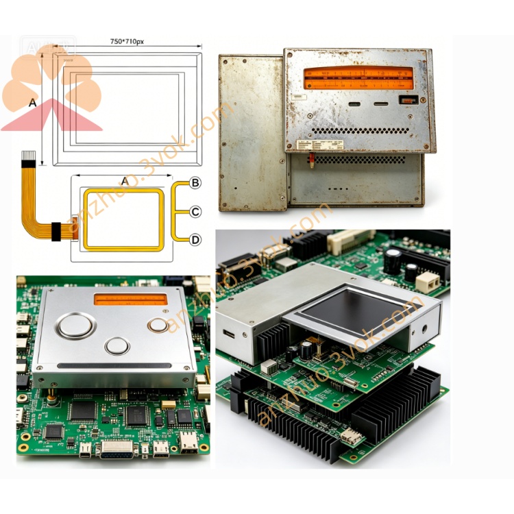
Adopts unified plug-in size for System 2003 series, compatible with all 7BP DIN rail backplanes (7BP701.1, 7BP702.0, 7BP703.0, 7BP704.0, 7BP707.0, 7BP708.0, 7BP709.0). It belongs to slave expansion equipment and can only be installed in slave slots behind the first CPU master slot of the backplane, cannot replace the CPU master position.
An integrated elastic snap lock at the bottom fixes the module on standard 35 mm DIN rails after full horizontal insertion until the front panel is flush with the backplane surface, no extra fixing brackets needed. The shell is flame-retardant reinforced industrial plastic made to Austrian standards, impact-resistant and anti-aging for long-term sealed cabinet operation. Protection class IP20, only applicable to closed indoor electrical cabinets; open air, water splashes and heavy dust environments are forbidden.
Multi-color LED indicators on the front panel display real-time status: power indication, backplane bus communication status, external fieldbus link status and fault alarm. Permanent laser marking on the casing contains B&R logo, part number 7CX408.50-1, hardware revision, unique factory serial number and "Made in Austria" mark for traceability and authenticity verification. Mechanical structure meets EN 60068-2-6 vibration and shock resistance standards tested at B&R Austria factory.
3. Electrical Specifications and Backplane Bus Communication
Working power 24 V DC, powered through the backplane internal power bus, voltage tolerance range 18 V DC ~ 30 V DC. Low power consumption, will not increase excessive load to the System 2003 rack power supply. No built-in backup battery, clock data uniformly managed by rack master CPU.
Realizes bidirectional data interaction with the rack CPU via System 2003 proprietary differential backplane bus, with hardware filtering and full galvanic isolation between backplane side and external fieldbus side, effectively isolating ground loop interference between cabinet internal control system and on-site field equipment. Built-in multi-layer protection circuits including overvoltage, overcurrent, reverse connection and ESD electrostatic protection to prevent damage caused by field wiring errors and surge voltage. All backplane plug pins are gold-plated for stable conduction and oxidation resistance under long-term vibration conditions. Every imported module passes full electrical aging and communication stability testing before leaving Austria.
4. Interface Definition and Core Communication Function
4.1 Internal Backplane Interface
Rear plug-in gold-plated bus connector, used to connect System 2003 backplane, responsible for receiving instruction data issued by master CPU and uploading fieldbus feedback data to the CPU, the only channel for data interaction between this interface module and the control rack.
4.2 External Fieldbus Interface
Front panel reserved standard bus wiring terminals, this model is designed for mainstream industrial fieldbus expansion, supporting stable communication with ACOPOS servo drives, touch screens, remote I/O stations, inverters and third-party automation equipment. It converts the internal backplane protocol of System 2003 into external standard bus protocol, acting as a protocol conversion bridge between rack CPU and field devices.
No analog input/output channels, no digital switching signal terminals, no encoder pulse receiving ports; the whole module only undertakes bus protocol conversion and signal transmission tasks, without independent logic operation and motion calculation capability, all operation logic relies entirely on the upper 7CP series master CPU.
5. Working Principle and Data Processing Flow
The rack master CPU sends control commands, motion parameters and setting values to 7CX408.50-1 through the backplane bus;
The interface module completes protocol conversion and signal isolation, then forwards data to external fieldbus slave devices;
Field equipment uploads operating status, position feedback, fault codes and real-time parameters back to the interface module via external bus;
The module converts fieldbus data into backplane bus format and transmits it to the master CPU for unified logic, PID and motion calculation processing;
The module feeds back its own communication link status and fault codes to the CPU in real time, and displays abnormal conditions through front panel fault LED.
6. Environmental Operating Conditions
Continuous operating temperature: 0 °C ~ +60 °C; storage and transportation temperature: -25 °C ~ +70 °C, exported with anti-static shockproof packaging from Austria.
Ambient humidity 5%–95% non-condensing. Cannot be used in environments with corrosive gas, long-term high humidity, heavy dust, liquid splashes and flammable explosive media; harsh workshops must adopt fully sealed ventilated control cabinets.
External fieldbus wiring must use shielded twisted-pair cables to guarantee long-distance communication stability and anti-interference ability.
7. Compatible System 2003 Hardware Matching Range
Matching Master CPU
All 7CP series System 2003 master CPUs: 7CP476 series, 7CP770 series, 7CP774 series and other full-range master controllers.
Matching Auxiliary Hardware
All 7BP DIN rail backplane models;
7AC020.9 blank slot baffles for unused slave positions;
Special 24 V DC rack power supply for System 2003 platform;
Matched shielded bus cables and terminal accessories.
Incompatible with B&R later generation platforms X20, X67, APC series, as well as third-party brand PLC backplane systems and non-B&R servo systems without protocol adaptation. Empty slave slots must be covered with 7AC020.9 baffles to stabilize bus impedance and prevent dust and pin oxidation from affecting communication quality.
8. Typical Industrial Application Scenarios
Plastic injection molding machines: expand bus communication channels for multi-axis ACOPOS servos, connect temperature and pressure remote monitoring instruments;
Packaging and filling equipment: link positioning servo drives, photoelectric detection remote I/O and man-machine touch screens;
Textile winding and drying machinery: communicate with spindle servo, tension control inverters and speed monitoring units;
CNC machining equipment: connect spindle servo, external tool detection I/O and operation panel;
Water treatment, conveyor assembly lines: link frequency converters, flow/pressure remote stations and safety monitoring modules.
It is widely used as an imported replacement spare part for aging System 2003 production lines, fully backward compatible with original rack configuration, no need to modify the overall control program architecture after replacement, only simple bus address parameter configuration in Automation Studio software is required.
9. Quality Assurance, Installation and Maintenance Specifications
Every authentic imported 7CX408.50-1 has an independent factory serial number archived in B&R Austria database for full supply chain traceability and authenticity inspection. Refurbished spare modules undergo strict pre-delivery testing: backplane plug vibration cycle test, 24 V voltage fluctuation aging, long-time fieldbus communication stability test, LED function verification and 72-hour continuous burn-in under high electromagnetic interference simulation environment. Qualified new and refurbished modules enjoy a standard supplier warranty of 12–24 months, supported by original factory quality records.
Standard Installation and Commissioning Steps
Mount 7BP backplane firmly on 35 mm DIN rail inside the cabinet, install 7CP master CPU in the first master slot and lock the buckle;
Insert 7CX408.50-1 into any idle slave slot behind the CPU, fasten the bottom snap lock;
Complete external fieldbus cable wiring according to terminal definition, use shielded twisted-pair and reasonably ground the shielding layer;
Power on the rack 24 V power supply, confirm module power LED lights normally;
Connect PC with licensed B&R Automation Studio to CPU programming port, enter the hardware configuration page to add 7CX408.50-1 module, set bus address, communication rate and protocol parameters;
Download the configured project to the master CPU, switch CPU to RUN mode;
Check module bus link LED is normally on, no fault alarm, conduct online communication test with external servo/HMI/I/O equipment to verify data receiving and transmitting normally.
Get a Quote