Bently Nevada 19000-20-34-36-02 Machinery Condition Monitor Product Specification
19000-20-34-36-02 is a factory preconfigured DIN rail mounted monitoring instrument belonging to Bently Nevada 19000 series modular monitor platform, originally manufactured in the United States for fixed customized configuration according to coded suffix definitions. Each numeric segment carries fixed factory-set specification: the base series 19000 stands for universal machinery protection monitor platform; code 20 defines dedicated wide range DC power supply specification; code 34 represents fixed onboard channel configuration layout; code 36 corresponds to integrated local digital display plus RS485 Modbus-RTU communication function; suffix code 02 approves Class I Division 2 hazardous area certification for explosive industrial site installation. Designed to cooperate with Bently eddy-current proximity probes, matched proximitor units, piezoelectric accelerometers and standard RTD/thermocouple temperature sensors, the monitor constructs complete TSI measurement loops for continuous online monitoring and safety interlock protection of critical rotating equipment across thermal power, petrochemical refining, metallurgy and large process pump industries. All internal printed circuit boards are covered with industrial conformal coating to guard against cabinet dust, humid air and mild corrosive industrial gas to sustain uninterrupted twenty-four-hour long-term operation inside control cabinets, widely used as direct replacement spare parts for legacy 7200 and early 1900 series monitoring system renovation and daily maintenance.
Description
Bently Nevada 19000-20-34-36-02 Machinery Condition Monitor Product Specification
1. General Product Overview
19000-20-34-36-02 is a factory preconfigured DIN rail mounted monitoring instrument belonging to Bently Nevada 19000 series modular monitor platform, originally manufactured in the United States for fixed customized configuration according to coded suffix definitions. Each numeric segment carries fixed factory-set specification: the base series 19000 stands for universal machinery protection monitor platform; code 20 defines dedicated wide range DC power supply specification; code 34 represents fixed onboard channel configuration layout; code 36 corresponds to integrated local digital display plus RS485 Modbus-RTU communication function; suffix code 02 approves Class I Division 2 hazardous area certification for explosive industrial site installation. Designed to cooperate with Bently eddy-current proximity probes, matched proximitor units, piezoelectric accelerometers and standard RTD/thermocouple temperature sensors, the monitor constructs complete TSI measurement loops for continuous online monitoring and safety interlock protection of critical rotating equipment across thermal power, petrochemical refining, metallurgy and large process pump industries. All internal printed circuit boards are covered with industrial conformal coating to guard against cabinet dust, humid air and mild corrosive industrial gas to sustain uninterrupted twenty-four-hour long-term operation inside control cabinets, widely used as direct replacement spare parts for legacy 7200 and early 1900 series monitoring system renovation and daily maintenance.
2. Application Scope
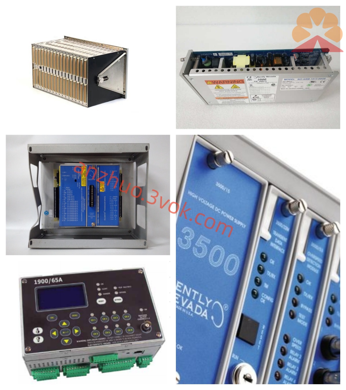
This integrated monitor fulfills multi-parameter centralized measurement for steam turbines, centrifugal compressors, large induced draft fans and heavy-duty feed pumps. Equipped with pre-defined dynamic input channels, it receives standard linear negative DC output signals from paired proximitor and eddy-current probe assemblies to measure non-contact radial shaft vibration, axial thrust displacement and rotor eccentricity of rotating shafts; meanwhile these dynamic channels can be reconfigured via supporting configuration software to process input signals from casing mounted velocity or acceleration vibration pickups for absolute housing vibration monitoring without any hardware replacement. Independent dedicated temperature channels collect real-time bearing bush temperature, motor winding temperature and equipment shell temperature from PT100 RTD sensors and industrial standard J, K, T, E type thermocouples. After internal signal conditioning, digital sampling and comparison with user programmable Alert and Danger threshold values, the monitor delivers multiple types of output signals: passive dry contact relay outputs trigger local audible and visual alarm devices as well as emergency equipment trip interlock circuits; galvanically isolated 4-20mA analog outputs transmit measured physical parameters to local field indicators and distributed DCS control systems; the built-in Modbus-RTU communication defined by code 36 enables digital transmission of real-time measured data, alarm status and historical fault logs to upper computer monitoring platforms and predictive maintenance management software for long-term trend tracking and equipment fault analysis. The front panel digital display specified by code 36 allows field maintenance personnel to read on-site real-time measurement data directly without connecting external configuration equipment.
3. Detailed Electrical Performance Specifications
3.1 Power Supply Parameters
Defined by configuration code 20, the unit adopts wide-range industrial DC power input design with rated working scope covering 18VDC to 32VDC and nominal operating voltage of 24VDC. Internal integrated multi-level protection circuits including reverse polarity prevention, transient surge suppression and overvoltage short-circuit protection effectively protect internal electronic components from damage caused by on-site miswiring or instantaneous power grid fluctuation. Optimized low-power circuit layout controls total full-load power consumption below 9W to restrict continuous operational heat generation, enabling stable long-time running inside compact sealed cabinet space without additional external cooling fans or auxiliary heat dissipation devices.
3.2 Input Channel Specifications
Code 34 corresponds to fixed factory channel arrangement combining multiple universal dynamic vibration input ports and independent temperature measurement ports. Every dynamic input channel is pre-calibrated at factory for standard AISI4140 alloy steel target with default sensitivity of 7.87V/mm to perfectly match output characteristic of Bently 19048 series proximity probes and supporting 19049-04 proximitor units, and users can switch channel measurement type among eddy displacement, acceleration and velocity mode through software setup only. All temperature input channels are equipped with embedded cold junction compensation circuit to eliminate ambient temperature drift interference on thermocouple measuring accuracy and guarantee stable temperature acquisition precision under variable cabinet environment. High-resolution analog-to-digital conversion circuits are adopted inside to restrain measurement error under complicated industrial electromagnetic interference generated by surrounding high-voltage cabinets and variable frequency drive equipment.
3.3 Output and Communication Functions
Various output terminals are reserved to satisfy diversified field wiring demands. Multiple groups of independent passive C-type dry contact relays are configured for Alert warning, Danger protection and channel fault indication respectively, each relay contact owns maximum rated load capacity of 250VAC/5A to directly drive on-site alarm equipment and safety interlock loops without intermediate isolation relays. Four-channel galvanically isolated 4-20mA analog outputs provide linear proportional signal corresponding to real-time measured values for remote data collection of DCS and local panel instruments. Following code 36 configuration, the monitor is fitted with standard RS485 hardware interface supporting Modbus-RTU industrial communication protocol to realize multi-drop bus networking connection for centralized digital data uploading. A spare buffered raw signal output port is arranged on terminal layout for convenient field debugging and periodic instrument calibration work.
3.4 Onboard Automatic Self-Diagnosis
Continuous background diagnostic program runs inside the monitor during full working period to monitor wiring integrity of all connected sensors and measuring cables. Once typical field faults including probe internal wire open-circuit, extension cable short-circuit, proximitor power failure or measured clearance out of calibrated linear range are detected, corresponding front panel fault indicator lamp will turn on and assigned fault relay will act synchronously; all abnormal event information and fault codes are automatically stored into internal nonvolatile memory for later maintenance review and failure root cause analysis.
4. Mechanical Structure and Environmental Working Ratings
4.1 Mechanical Installation Specification
The monitor is designed as compact modular structure compatible with standard top-hat DIN rail for quick snap-in installation inside indoor industrial control cabinets. The outer enclosure is made of flame-retardant high-strength engineering plastic; front panel integrates digital display window, multiple LED status indicators and function operation buttons, while side terminal area arranges orderly screw-type terminal blocks for power supply access, sensor signal input and external output wiring connection. Reinforced anti-vibration soldering process is applied on all PCB component solder joints to resist periodic mechanical vibration transmitted from adjacent running production equipment and ensure long-term structural stability of internal circuits.
4.2 Ambient Operating Limits
Rated continuous working ambient temperature ranges from -20°C to +70°C for regular indoor control room and semi-enclosed field cabinet installation near rotating equipment; permissible storage and transportation temperature spans from -40°C to +85°C to adapt cross-regional spare part logistics and long-term warehouse inventory storage under different seasonal climate conditions. Allowed working relative humidity is controlled between 5% and 95% under non-condensing condition to avoid internal PCB short-circuit damage caused by cabinet dew condensation and accumulated moisture. With Class I Division 2 hazardous area certification marked by suffix code 02, the monitor can be safely installed inside classified explosive gas and dust hazardous locations of petrochemical and oil-gas factories; open-air exposed installation without extra sealed protective housing is prohibited.
5. Core Product Technical Advantages
First, integrated multi-channel layout combining vibration and temperature measurement reduces required cabinet installation space and simplifies field wiring construction workload during old monitoring system upgrading projects. Second, full software configurable channel function avoids unnecessary hardware replacement when switching different kinds of connected sensors, effectively cutting end users’ spare part stocking varieties and subsequent maintenance cost. Third, multi-form output design covering relay hard-wired interlock, isolated analog signal and digital Modbus communication achieves seamless access to both traditional protection loop and modern intelligent DCS centralized control system. Fourth, onboard local digital display and complete self-diagnosis function greatly shorten on-site troubleshooting time and lower unexpected equipment downtime induced by undetected measuring circuit failure. Fifth, hazardous area certification of code 02 expands applicable working scenarios to conventional power plants as well as explosion-prone chemical and refining facilities, and unified factory calibration standard with matching Bently proximity transducer series ensures good interchangeability for field spare replacement maintenance.
6. Certification and Warranty Terms
19000-20-34-36-02 is original US-produced Bently Nevada industrial component conforming to internal factory quality control standards, CE electrical safety certification and Class I Division 2 hazardous location certification specified by code 02, complying with API670 standard for rotating machinery protection. When installed and operated strictly within stipulated electrical and environmental operating parameters without artificial physical damage, improper power wiring or overvoltage abuse, the product enjoys standard twelve-month limited factory warranty covering inherent original manufacturing defects calculated from formal goods delivery date.
Get a Quote