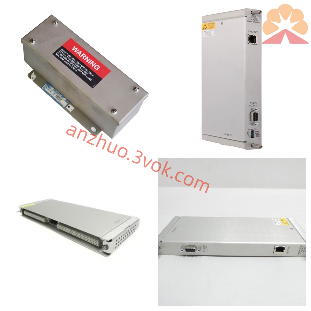
Bently Nevada 135145-01 Rear I/O Termination Module for 3500/45 Position Monitor
135145-01 is original US-manufactured dedicated rear termination I/O accessory exclusively matched with Bently Nevada 3500/45 four-channel position monitoring front card within the 3500 series TSI rotating machinery protection system, specified as external termination variant without onboard intrinsic safety barrier circuit and limited to non-hazardous safe-area cabinet installation only. It is mounted into standard single-width rear slot of 3500/05 system rack and draws full operational power from rack internal backplane bus without separate external DC power feed; hot-swap compatible design allows live plug-and-replacement under continuous rack powered state without interrupting position signal collection of monitored turbomachinery equipment. Serving as core physical signal bridge between field-installed displacement transducers and front-side 3500/45 monitor card, the module completes sensor excitation power distribution, raw position signal transmission and 4–20mA analog output terminal wiring, with no independent data protocol conversion or direct DCS network access function.
Description
Bently Nevada 135145-01 Rear I/O Termination Module for 3500/45 Position Monitor
1. Product Overview
135145-01 is original US-manufactured dedicated rear termination I/O accessory exclusively matched with Bently Nevada 3500/45 four-channel position monitoring front card within the 3500 series TSI rotating machinery protection system, specified as external termination variant without onboard intrinsic safety barrier circuit and limited to non-hazardous safe-area cabinet installation only. It is mounted into standard single-width rear slot of 3500/05 system rack and draws full operational power from rack internal backplane bus without separate external DC power feed; hot-swap compatible design allows live plug-and-replacement under continuous rack powered state without interrupting position signal collection of monitored turbomachinery equipment. Serving as core physical signal bridge between field-installed displacement transducers and front-side 3500/45 monitor card, the module completes sensor excitation power distribution, raw position signal transmission and 4–20mA analog output terminal wiring, with no independent data protocol conversion or direct DCS network access function.
This termination card is engineered for multi-type position sensor signal adaptation, supporting field wiring connection with eddy current proximity probes, rotary position transducers (RPT) and DC LVDT linear displacement sensors, which are commonly deployed to measure shaft axial thrust, differential expansion, casing thermal expansion and regulating valve stem displacement on large rotating equipment. Differentiated from intrinsically safe rear I/O series like 135473 and 135489, 135145-01 excludes built-in explosion-proof safety limiting components and must use external safety barrier accessories if required for field hazardous location wiring layout.
2. Core Functional Description
The module adopts four independent signal channel layout in one-to-one correspondence with channel configuration of paired front 3500/45 position monitor, realizing separate signal routing for four groups of field position sensors simultaneously. It distributes regulated DC excitation power to connected proximity probes and LVDT transducers, forwards conditioned raw displacement signals via rack backplane bus to front monitor for analog-to-digital conversion, position value calculation and threshold comparison for pre-alarm and trip protection logic judgment. All channel input circuits integrate built-in ESD and surge suppression components to defend against transient overvoltage damage caused by field wiring misconnection and electromagnetic interference from adjacent high-current power cables.
Dedicated screw terminal partitions are reserved for scaled 4–20mA analog output signals converted from measured displacement parameters, enabling direct hardwire connection with plant DCS, PLC and on-site data acquisition systems for real-time position trending and historical data archiving. Auxiliary grouped dry contact wiring terminals match alarm relay logic defined on front monitor card, supporting external connection of local annunciators and equipment emergency shutdown interlock circuits; all alarm threshold parameters including high pre-alarm and critical trip limit are configured via official 3500 system configuration software on front monitoring hardware.
Embedded continuous self-diagnostic circuitry runs real-time monitoring of sensor open-circuit fault, terminal short-circuit failure and backplane communication abnormal status; all fault codes with timestamped event records are uploaded through backplane bus to front monitor unit, 3500/93 local display panel and upper-level System 1 centralized monitoring platform. Edge-mounted status LED indicators deliver intuitive visual feedback of channel power supply status, normal signal running state and internal circuit fault warning to simplify routine field inspection and rapid fault troubleshooting work. Non-volatile onboard memory retains historical fault logs without data loss during short-time cabinet power drop or instantaneous power outage for later maintenance trace analysis.
3. Physical Interface and Mechanical Specification
All field external wiring terminals adopt standard industrial screw-type terminal blocks centrally arranged on module rear outer surface, split into three independent terminal districts: four-channel transducer input terminal group for proximity/LVDT/RPT sensor wiring, independent terminal set for 4–20mA analog output routing, and reserved auxiliary terminals for auxiliary alarm signal outgoing wiring. Front edge of the module is equipped with gold-plated edge connector complying with unified 3500 rack backplane specification to realize stable power intake and bidirectional high-speed data communication with matched front-side 3500/45 monitor without extra intermediate adapter fittings. Elastic locking buckles fixed on both vertical sides of module metal housing fasten the card tightly inside rack rear slot to avoid poor contact induced by long-term cabinet vibration from surrounding running large rotating machinery.
Overall mechanical dimension follows universal single-width specification of 3500 series rear I/O modules: 241.3mm height, 24.4mm width and 99.1mm installation depth; net product weight is controlled around 0.20kg per factory standard parameter. Full PCB surface is coated with three-proof conformal insulating paint to resist erosion from cabinet internal oil mist, condensed moisture and trace corrosive industrial gas; structural reinforcement optimization improves mechanical shock resistance and long-term operational stability under continuous vibration industrial cabinet environment.
4. Electrical and Environmental Technical Parameters
The module operates entirely on centralized 24VDC ±10% working voltage supplied via rack backplane bus, with typical full-load total working current around 95mA and maximum overall power consumption lower than 1.0W under full four-channel field wiring condition. Every signal input terminal is fitted with independent transient overvoltage suppression and ground isolation design to effectively eliminate ground loop interference existing in complex industrial wiring environment, complying with CE EMC anti-interference certification and API670 international turbomachinery protection standard requirements.
Rated continuous working ambient temperature ranges from -30℃ to +65℃ for stable long-term running; short-duration intermittent peak temperature up to +75℃ will not trigger irreversible damage to internal electronic components. Applicable working relative humidity covers 5%RH~95%RH under non-condensing condition to adapt high-dust and high-humidity conventional power, petrochemical and metallurgical control cabinet operating scenarios. Spare part specified storage temperature spans -40℃ ~ +85℃, requiring dry sealed warehouse storage away from acid-base corrosive vapor, liquid immersion and violent mechanical collision damage. Without intrinsic safety certification, this module is prohibited for direct wiring connection to field sensors installed inside Class I Division or Zone classified explosive hazardous locations.
5. Version Differentiation from Related Serial Models
Within 3500 system rear I/O product lineup, 135145-01 is exclusive non-intrinsic-safety termination accessory specially customized for 3500/45 position monitor, functionally different from 135473 Keyphasor dedicated rear I/O and 135489 proximity intrinsic safety rear I/O which target phase signal and vibration sensor wiring separately and carry built-in safety barrier for hazardous area deployment, resulting in non-interchangeable rack installation among these part numbers. Base part number 135145-01 stands for bare unpacked spare module without original factory anti-static sealed packaging; finished factory-sealed complete product with full outgoing inspection documents and original factory test reports is marked with suffix-P at part number tail. Other derivative suffix variants feature adjusted terminal layout or partial circuit optimization and cannot be arbitrarily cross-replaced with standard 135145-01 on rack slot installation.
6. Industrial Application Scope
135145-01 is core matched rear wiring component widely used in global energy industry TSI protection projects, core application scenarios include axial thrust and differential expansion monitoring cabinet configuration for steam turbine generator units of thermal power plants, casing expansion and compressor valve displacement signal collection for large centrifugal compressors and hydrogen compressors in petrochemical and coal chemical non-hazardous control rooms, critical feed pump and blower shaft position parameter monitoring inside metallurgical heavy industry production lines, as well as turbomachinery condition monitoring cabinet deployment for onshore and offshore oil & gas production platforms in safe-area control buildings. It forms indispensable intermediate wiring link between rack position monitoring hardware and field displacement transducer loops, providing accurate position benchmark for unit safety protection and automatic emergency shutdown logic execution of critical rotating equipment.
7. Factory Inspection and Warranty Regulation
Each brand-new original 135145-01 undergoes comprehensive pre-delivery factory verification including four-channel terminal continuity test, signal circuit parameter precision calibration, long-period continuous power-on burn-in aging test and high-low temperature cyclic reliability screening experiment to confirm all electrical and mechanical parameters fully comply with US original factory design specification. Manufacturer’s standard commercial warranty period lasts twelve months calculated starting from formal product delivery date; free repair or replacement service is available for hardware failures originating from inherent manufacturing defects when the module is installed and operated within rated environmental and electrical parameter scope during valid warranty period. Product damage caused by unauthorized housing disassembly, incorrect field terminal wiring, external lightning surge overvoltage impact, artificial mechanical collision and chemical medium corrosion is excluded from all free warranty coverage scope.
Get a Quote