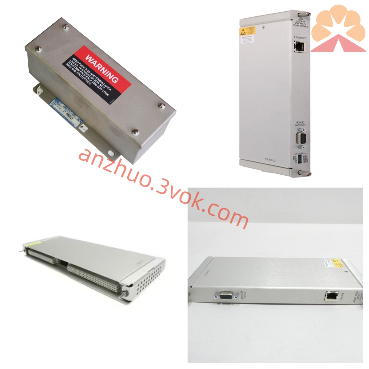
Bently Nevada 135489-04 Four-Channel Internal Barrier Rear I/O Module for 3500/40M Proximity Monitor
135489-04 is a factory original rear termination I/O accessory exclusively engineered to pair with the Bently Nevada 3500/40M four-channel proximity monitor front card within the 3500 series TSI rotating machinery protection system manufactured in the United States. Distinguished from non-barrier variants such as 135489-01, 135489-02 and 135489-03, this unit features integrated intrinsic safety barriers built directly onto the printed circuit board, eliminating the requirement for separate external barrier devices for hazardous area field wiring applications. The module is installed into the corresponding rear slot of a standard 3500/05 equipment rack, receiving all required operating power via the rack’s internal backplane bus without any independent external power source, and it supports hot-swap replacement while the rack remains energized without interrupting continuous vibration and position protection logic for monitored critical machinery. Serving as the sole physical wiring transition bridge between field-installed eddy-current proximity probes and the front 3500/40M monitor card, it is purpose-built for signal routing of 3300XL series proximity transducers deployed across petrochemical, refining and offshore gas hazardous classified locations and is not designed for industrial communication protocol conversion or direct DCS networking functions.
Description
Bently Nevada 135489-04 Four-Channel Internal Barrier Rear I/O Module for 3500/40M Proximity Monitor
1. Product Overview
135489-04 is a factory original rear termination I/O accessory exclusively engineered to pair with the Bently Nevada 3500/40M four-channel proximity monitor front card within the 3500 series TSI rotating machinery protection system manufactured in the United States. Distinguished from non-barrier variants such as 135489-01, 135489-02 and 135489-03, this unit features integrated intrinsic safety barriers built directly onto the printed circuit board, eliminating the requirement for separate external barrier devices for hazardous area field wiring applications. The module is installed into the corresponding rear slot of a standard 3500/05 equipment rack, receiving all required operating power via the rack’s internal backplane bus without any independent external power source, and it supports hot-swap replacement while the rack remains energized without interrupting continuous vibration and position protection logic for monitored critical machinery. Serving as the sole physical wiring transition bridge between field-installed eddy-current proximity probes and the front 3500/40M monitor card, it is purpose-built for signal routing of 3300XL series proximity transducers deployed across petrochemical, refining and offshore gas hazardous classified locations and is not designed for industrial communication protocol conversion or direct DCS networking functions.
2. Core Functional Description
The module provides fully separated signal routing for four independent measuring channels matching the channel layout of its paired 3500/40M front monitor card. It supplies regulated -24VDC excitation power to field-mounted proximity probe and preamplifier assemblies while receiving modulated carrier signals for radial shaft vibration, axial thrust displacement, rotor eccentricity and differential expansion measurement. All field-side signal paths pass through onboard intrinsic safety barriers to limit voltage and current energy transferred into hazardous rated environments in compliance with intrinsic safety design standards before signal transmission across the rack backplane to the front monitor for digital conversion and parameter calculation. Each individual channel includes dedicated terminal points for isolated 4–20mA analog output signals converted from measured displacement and vibration values, enabling straightforward hardwired connection to plant DCS and data acquisition systems for continuous real-time parameter tracking. Pre-alarm and danger trip dry contact outputs grouped at dedicated terminal positions are routed from front-card configured threshold logic via backplane signals, allowing direct field wiring to local alarm annunciators or equipment emergency shutdown interlock circuits. Onboard diagnostic circuitry continuously monitors for open-circuit probe faults, transducer short-circuit conditions and internal barrier component failures, with all detected fault codes transmitted to the front monitor, local 3500/93 display unit and upper-level configuration platforms; non-volatile onboard memory retains historical fault event logs that remain intact during brief cabinet power fluctuations or momentary power loss for later maintenance review. Multiple status LED indicators on the module edge deliver quick visual indication of channel power status, active measurement operation and internal barrier fault conditions to streamline routine on-site equipment inspection and troubleshooting work.
3. Physical Interface and Mechanical Specification
All field wiring terminals are arranged on screw-type terminal blocks positioned on the external rear-facing side of the module, including dedicated terminals for four-channel proximity transducer wiring, four-channel 4–20mA analog signal output wiring and centralized terminals for pre-alarm and danger relay dry contact connections. The front edge of the card is equipped with gold-plated edge connectors built to comply with the unified 3500 rack backplane specification, establishing stable power feed and bidirectional data communication with the matched front 3500/40M monitor card without additional intermediate adapter hardware. Spring locking latches integrated along both vertical edges of the module secure the card firmly inside the rack rear slot and prevent intermittent connector contact resulting from persistent cabinet vibration generated by nearby operating large-scale rotating equipment. The overall mechanical dimensions follow the universal single-width form factor of all standard 3500 series rear I/O modules, with standardized height, width and installation depth matching the dimensional specification of the entire product family, and its net weight varies slightly according to internal barrier component configuration. The entire PCB assembly is fitted with reinforced fixed structural design to improve mechanical stability under continuous industrial cabinet vibration environments.
4. Electrical and Environmental Technical Parameters
Operating power is derived entirely from the centralized rack power supply unit via backplane bus, with total full-load power consumption maintained within the factory specified rated limit under fully wired four-channel operating conditions. Every field-connected terminal path is protected by integrated intrinsic safety barrier circuits alongside supplementary ESD and transient surge suppression components to block destructive instantaneous overvoltage induced by field wiring errors, cable short circuits or lightning electromagnetic induction. The intrinsic safety barrier layout conforms to internationally recognized explosion-proof intrinsic safety standards for installation in Class I Division 2 hazardous classified industrial areas, eliminating extra barrier installation costs and simplifying field cabinet wiring arrangement. The complete printed circuit board is coated with high-performance conformal three-proof insulating paint to defend internal circuitry against corrosive volatile gas, condensed moisture and oil mist commonly found inside thermal power turbine houses, petrochemical refining control cabinets and offshore platform electrical rooms.
For ambient working specifications, the rated continuous operating temperature range covers standard industrial ambient limits for long-term stable service, while intermittent short-duration peak temperature exposure is permissible within a defined upper threshold without inducing permanent component drift or irreversible hardware degradation. The allowable working relative humidity spans from 5%RH to 95%RH under non-condensing environmental conditions to accommodate high-humidity, high-dust and oil-laden industrial cabinet surroundings. During spare part storage, the specified storage temperature range requires dry sealed warehouse placement away from acidic or alkaline corrosive vapors, liquid immersion and severe mechanical impact damage. The finished product passes formal CE EMC electromagnetic compatibility testing and industrial anti-vibration endurance verification to satisfy API670 global rotating machinery protection standard requirements.
5. Version Differentiation from Related Part Numbers
135489-04 is the unique integrated intrinsic safety barrier model within the 135489 rear I/O product series, specifically designated for hazardous area installation. 135489-01, 135489-02 and 135489-03 are non-barrier standard rear termination variants intended exclusively for non-hazardous safe-area cabinet installation and cannot be directly substituted for 135489-04 on intrinsically classified field sites without supplementary external safety barrier installation. Factory sealed original packaged units carry suffix P marking while bare unpacked spare stock is issued under the base 135489-04 part number without original factory anti-static packaging; no standard modified offshore reinforced derivative version is released for this base part number.
6. Industrial Application Scope
This rear I/O module is a standard matched component for 3500/40M proximity monitor cards across global energy industries. Core implementation scenarios include TSI protection system configuration for steam turbine generator units in thermal power facilities, axial displacement and vibration monitoring for large centrifugal and hydrogen compressors at petrochemical and coal chemical production sites, critical pump and blower mechanical protection for metallurgical manufacturing lines, and hazardous area machinery monitoring on offshore oil and natural gas production platforms. It forms the essential field wiring interface for all proximity-based position and vibration measurement loops within hazardous classified control cabinets.
7. Factory Inspection and Warranty Terms
Each brand-new original 135489-04 undergoes comprehensive pre-shipment factory validation including full-channel terminal continuity testing, intrinsic safety barrier characteristic calibration, long-duration continuous power-on burn-in aging and high-low temperature cyclic reliability screening to confirm all electrical and mechanical parameters conform to original US factory design specifications. The manufacturer’s standard warranty period runs for twelve months starting from formal product delivery date; complimentary repair or replacement service is available for hardware failures stemming from verified inherent manufacturing defects when operated within rated installation and environmental limits during valid warranty coverage. Product damage caused by unauthorized enclosure disassembly, incorrect field wiring configuration, external lightning surge overvoltage, artificial physical collision and chemical medium corrosion is excluded from all free warranty provisions.
Get a Quote