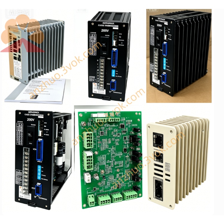
CACR-SR05SZ1SS-Y85
CACR represents Yaskawa classic Yasnac VS800 full digital AC SERVOPACK servo amplifier product series. SR stands for universal servo driver supporting switchable position, speed and torque control via internal parameter setup. 05 refers to 0.5kW rated matching servo motor power specification. S means S-version main control PCB with dedicated peripheral circuit for serial absolute encoder signal processing. Z denotes built-in hardware circuit for multi-turn absolute encoder plus integrated internal dynamic braking module; it keeps absolute position data after power loss so homing is unnecessary after equipment restarts. 1 specifies three-phase AC200V~230V, 50/60Hz main input power standard. The first S indicates CN2 feedback port designed for differential serial multi-turn absolute encoder. The second S defines standard digital differential pulse as primary positioning command and universal standard I/O base definition. Y85 is exclusive OEM factory customized code, with factory pre-set fixed I/O logic and locked group of operating parameters specially optimized for designated host machine; core customized parameters shall not be modified arbitrarily without mechanical structural change of matched equipment.
Description
1. Model Code Definition
CACR represents Yaskawa classic Yasnac VS800 full digital AC SERVOPACK servo amplifier product series. SR stands for universal servo driver supporting switchable position, speed and torque control via internal parameter setup. 05 refers to 0.5kW rated matching servo motor power specification. S means S-version main control PCB with dedicated peripheral circuit for serial absolute encoder signal processing. Z denotes built-in hardware circuit for multi-turn absolute encoder plus integrated internal dynamic braking module; it keeps absolute position data after power loss so homing is unnecessary after equipment restarts. 1 specifies three-phase AC200V~230V, 50/60Hz main input power standard. The first S indicates CN2 feedback port designed for differential serial multi-turn absolute encoder. The second S defines standard digital differential pulse as primary positioning command and universal standard I/O base definition. Y85 is exclusive OEM factory customized code, with factory pre-set fixed I/O logic and locked group of operating parameters specially optimized for designated host machine; core customized parameters shall not be modified arbitrarily without mechanical structural change of matched equipment.
2. Electrical Specifications
Main circuit input adopts three-phase AC200V~230V with allowable voltage fluctuation of -15%~+10% and adapts to 50Hz and 60Hz power frequency. Independent single-phase AC200~230V terminals are available for separated control circuit power supply. Rated continuous output power is 0.5kW and rated continuous output current is 3.2A. The driver can sustain 300% peak overload current of 9.6A for maximum 3 seconds and 150% rated overload within continuous 60 seconds. Nominal DC bus voltage ranges DC280V~320V, and P/N reserved terminals are prepared for external regenerative braking resistor connection for high-cycle frequent deceleration heavy-load working conditions.
3. Environmental and Mechanical Specifications
Permissible operating ambient temperature ranges from 0℃ to +55℃; short-time peak working temperature shall not exceed 60℃, while storage temperature spans -20℃~+70℃. Working relative humidity remains 5%~80%RH without condensation. Protection grade is IP20 and vertical cabinet installation is mandatory. Net weight is approximately 2.0kg, maximum applicable installation altitude is limited within 1000 meters above sea level, and the unit is resistant to 10~55Hz vibration with 0.5mm single amplitude.
4. Control Performance
The servo uses IGBT sine-wave PWM dual closed-loop control consisting of speed loop and position loop. Speed adjustable ratio reaches 1:5000 with full-load steady-state speed control accuracy within ±0.01%. Digital differential pulse serves as primary position command with maximum input frequency up to 500kpps, while analog speed and torque signal is reserved as auxiliary alternative control input. CN2 port is exclusively compatible with Yaskawa serial multi-turn absolute encoder to realize power-off position memory function. Built-in digital notch filter suppresses mechanical resonance and operational vibration. Three control modes can be switched freely through available parameters; gain, acceleration and deceleration parameters customized for Y85 version are pre-locked by factory setting to match original machine inertia and transmission characteristic.
5. Interface and Communication Configuration
R/S/T terminals are for three-phase main AC power input; U/V/W terminals connect three-phase power cable of matched servo motor; P/N spare terminals are used for external regenerative brake resistor wiring. CN1 is opto-isolated digital I/O terminal block equipped with 8 input channels and 6 relay output channels, all signal assignment follows fixed Y85 OEM customized definition including servo enable, forward/reverse overtravel limit, home origin input, emergency stop, servo ready output and fault alarm output. CN2 is dedicated connector for multi-turn absolute encoder feedback wiring. Onboard RS422 serial port adopts Yaskawa proprietary communication protocol for parameter reading & writing and real-time running status monitoring; optional expansion accessory supports Modbus-RTU bus communication to connect upper PLC control system.
6. Core Functions
Position, speed and torque three control modes can be flexibly switched, and electronic gear ratio setup enables multi-axis synchronous linkage for automated production equipment. Automatic motor parameter identification completes one-click detection of motor resistance, inductance and rotor inertia to automatically optimize closed-loop gain and shorten field debugging period. Absolute position storage eliminates mandatory homing after power cut and improves production efficiency. Internal integrated braking circuit absorbs most regenerative energy during motor deceleration; external braking resistor is only needed for frequent heavy-duty emergency stop application. Segmented gain parameter configuration ensures smooth low-speed running and fast high-speed dynamic response. The drive automatically saves latest 10 groups of historical fault codes for later maintenance troubleshooting. Y85 preconfigured parameters are calibrated for specified OEM equipment; random modification of locked parameters is forbidden unless mechanical structure is altered.
7. Applicable Scenarios
This Y85 customized servo drive is specially tailored for precision automatic equipment requiring absolute position retention after power outage, mainly including dedicated small CNC auxiliary feed axes, customized electronic component assembling equipment, miniature gantry positioning platform and special automated labeling production line. Equipment maintenance replacement requires identical full part number CACR-SR05SZ1SS-Y85.
8. Operation and Routine Maintenance Instructions
Before power-on, inspect all power cables, absolute encoder wires and I/O signal wiring to exclude short circuit, loose terminals and wrong connection risks. Complete motor parameter matching and load debugging in accordance with on-site mechanical condition and avoid arbitrary revision of factory-locked Y85 customized parameters. Ensure cabinet ventilation stays unobstructed during operation; prohibit long-time continuous running when inner cabinet temperature exceeds 55℃ and prevent frequent repeated power on/off within short time. Conduct regular maintenance every three to six months: tighten all terminal screws, inspect cable insulation aging and clean accumulated dust on drive heat sink and cabinet air duct. Cut off main AC power and wait at least 15 minutes for full discharge of internal DC bus capacitor before any internal disassembly maintenance to avoid electric shock hazard. Cut off power and stop equipment immediately upon continuous fault alarm, then check servo motor, connecting cables and mechanical jamming before restarting operation.
9. Basic Troubleshooting
Overheat alarm is commonly caused by blocked heat sink, excessive cabinet ambient temperature or long-term continuous overload operation. Encoder fault alarm usually comes from loose CN2 connector or damaged absolute encoder feedback cable. Overvoltage fault occurs under frequent rapid deceleration with heavy load; install external regenerative braking resistor on P/N terminals to solve the problem.
Get a Quote