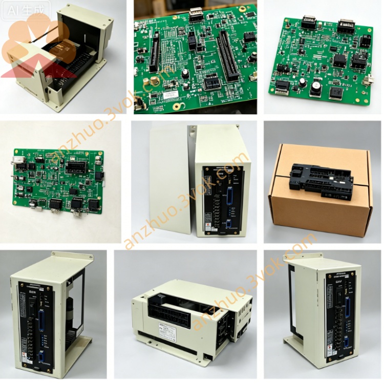
CACR-SR05BZ1SS
Description
1. MODEL CODE DEFINITION
2. ELECTRICAL SPECIFICATIONS
2.1 Power Rating
Main circuit input: 3Ø AC200~230V, allowable tolerance +10%/-15%, 50/60Hz
Control auxiliary power: Independent single-phase AC200~230V input
Rated continuous output: 0.5kW, continuous RMS output current = 3.2A; peak overload 9.6A (300% overload for max 3s)
DC bus nominal voltage: DC280~320V; P/N terminals reserved for external regenerative braking resistor for high-cycle deceleration loads
2.2 Ambient & Mechanical Data
Operating temperature: 0℃ ~ +55℃; storage temp: -20℃ ~ +70℃
Humidity: 5%~90%RH non-condensation; protection grade IP20 (cabinet installation only)
Mounting: vertical wall fixed installation; net weight ≈2.0kg; max working altitude ≤1000m
Vibration withstand: 10~55Hz, 0.5mm single amplitude
2.3 Control Performance
Control scheme: IGBT sine-wave PWM dual closed-loop (speed + position loop vector control)
Speed regulation range: 1:5000; steady-state speed accuracy ≤±0.01% full load
Position command input: 5V differential pulse (CW/CCW or Pulse+Dir), max input frequency 500kpps (S suffix core: prioritize digital pulse command instead of analog dominant of F model)
Feedback: Multi-turn serial absolute encoder (Z feature), power-off position memory without origin reset; compatible SGM/SGMF old-series Yaskawa absolute servo motor
Built-in notch filter to suppress mechanical resonance vibration
2.4 Full Protection Functions
3. TERMINAL & CONNECTOR DESCRIPTION
3.1 Main Power Terminals
3.2 Signal Connectors
3.3 Command Interface Feature
Primary command: Digital differential pulse position input (core of double-S suffix); secondary available analog ±6V speed / ±3V torque auxiliary input
Onboard Yaskawa exclusive RS422 serial communication: Parameter upload/download, real-time status monitoring, historical fault record reading; optional expansion for Modbus-RTU networking
4. KEY PRODUCT FUNCTIONS
Three control mode free switching: Position mode for precision fixed positioning; speed mode for constant-speed transmission; torque mode for tension winding; electronic gear ratio for multi-axis synchronous linkage
Auto motor parameter identification: One-click self-tuning to measure motor resistance, inductance & rotor inertia, auto optimize loop gain to shorten on-site debugging
Absolute position memory (Z feature): No mechanical homing after power outage, improves equipment operation efficiency
Internal integrated dynamic brake circuit: Internal module absorbs regenerative energy during deceleration; external resistor only needed for frequent heavy-duty emergency stop
Multi-segment gain setting: Separated low/high speed loop gain parameters for smooth low-speed running and rapid high-speed response; stores latest 10 fault codes for maintenance inquiry
5. APPLICATION SCENARIOS
6. OPERATION & MAINTENANCE GUIDE
6.1 Pre-Power Check
6.2 Daily Operation
6.3 Periodic Maintenance (3~6 months cycle)
7. COMMON FAULT TROUBLESHOOTING
Overheat alarm: Blocked heatsink, excessive cabinet temperature or long-term overload running
Encoder error alarm: Loose CN2 plug, damaged absolute encoder feedback cable
Overvoltage alarm: Frequent rapid deceleration under heavy load; install external brake resistor on P/N terminals
Get a Quote