
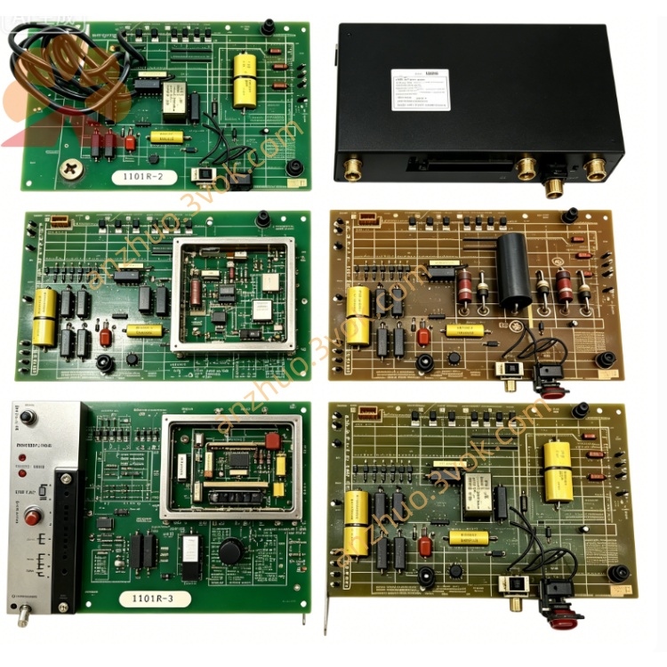
Reliance Electric 0-51864-2 CGSA Current Gate Board
Description
Product Introduction
Model Interpretation
Technical Parameters
Function: Current gate control and SCR firing signal generation.
Compatibility: Designed for Reliance Min‑Pak and related DC drive systems.
Power: Operates from the drive’s internal control power supply.
Components: Integrates precision resistors, capacitors, transistors, and a dedicated gate drive transformer.
Adjustments: Equipped with potentiometers for calibrating current loop gain and gate pulse timing.
Protection: Features onboard fuses and surge suppression for fault protection.
Environment: Industrial grade; operating temperature -20°C to +60°C, non‑condensing humidity.
Construction: Printed circuit board (PCB) with through‑hole components; designed for chassis mounting.
Interface and Communication Configuration
Power Interface: Connects to the drive’s internal DC power rails via dedicated edge connectors.
Signal Interface: Uses multi‑pin headers to receive speed reference, current feedback, and enable signals from the main control board.
Output Interface: Sends isolated gate drive pulses directly to the SCR power stack.
Communication: This is a hardware‑only control board with no network communication ports. All signals are hardwired within the drive cabinet.
Core Functions
Provides precision current regulation by generating accurate firing pulses for SCR rectifiers.
Stabilizes DC motor current and torque under varying load conditions.
Adjusts current loop response via onboard potentiometers for optimal performance.
Offers overcurrent protection by monitoring and limiting SCR gate signals.
Interfaces with the main drive control board to coordinate speed and current loops.
Application Scenarios
Legacy DC Drive Maintenance: Primarily used as a replacement part for Reliance Min‑Pak and similar DC drives in industrial facilities.
Industrial Motor Control: Applied in systems requiring precise DC motor speed and torque control, such as conveyors, extruders, winders, and cranes.
Retrofit Projects: Utilized in the repair and upgrade of older production lines where replacing the entire drive is cost‑prohibitive.
Operation and Maintenance Instructions
Safety: Disconnect all power to the drive before installation or removal. Allow capacitors to discharge fully before handling the board.
Installation: Align the board with the chassis slots and securely seat all edge connectors. Torque mounting screws to the manufacturer’s specification.
Calibration: During commissioning, adjust the potentiometers for current loop gain and gate pulse timing according to the drive’s manual and motor nameplate data.
Maintenance: Keep the board clean and free of dust. Inspect connectors for corrosion or loose wires periodically.
Troubleshooting: If the drive experiences current instability or SCR misfiring, inspect the board for damaged components or burnt traces. Replace the board if faults are found.
Get a Quote