
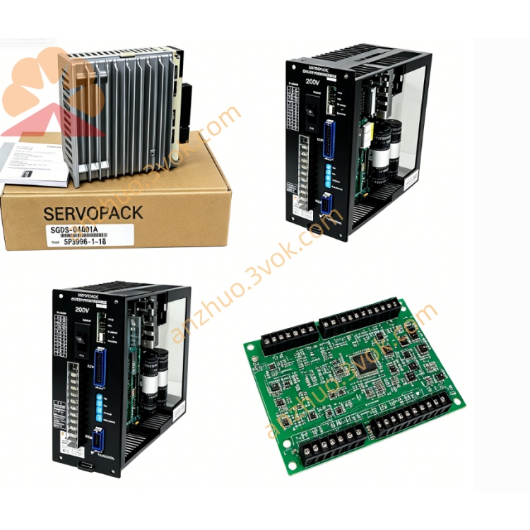
Yaskawa CACR-SR20BB1CS-Y114 Digital Servo Drive
The CACR-SR20BB1CS-Y114 is a digital AC servo drive of Yaskawa CACR-SR (VS-800) series, applied to CNC machine tools and industrial automation control systems. It adopts built-in forced air cooling, with 14.7 A continuous current and 35 A short-term peak current. Equipped with special communication interface, dedicated signal circuit and Y114 customized OEM parameter group, this drive features strong anti-interference capability and optimized running parameters, suitable for standard servo matching and automated production lines requiring fixed parameter configuration.
Description
Model Definition
CACR: AC servo drive (SERVOPACK) product familySR: VS-800 series for speed and position integrated control20: 2.0 kW rated output powerB: Three-phase 200–230 VAC main power supplyB: Standard hardware configuration for general industrial scenarios1: Single-phase 200 VAC control power supplyC: Special signal and control circuit designS: Dedicated communication interface moduleY114: Dedicated OEM parameter set preconfigured for specific application equipment
Technical Specifications
Electrical Parameters
Main power supply: 3-phase 200–230 V AC, tolerance -15% to +10%, 50/60 HzControl power supply: 1-phase 200–230 V AC, tolerance -15% to +10%, 50/60 HzDC bus voltage: Internal integrated DC bus circuitContinuous output current: 14.7 APeak output current: 35 A for short-time operationOutput frequency range: 0 Hz to 400 HzPower dissipation: Approximately 120 WCompatible motors: Yaskawa S-series servo motors equipped with incremental encoders
Mechanical & Environmental Parameters
Cooling method: Built-in forced air cooling with internal fanProtection class: IP20 for the whole unitOperating temperature: 0 °C to +55 °CStorage temperature: -20 °C to +85 °CMaximum installation altitude: 1000 m, 1% performance derating per 100 m above 1000 mVibration resistance: 0.5 g (10–60 Hz), 0.2 g (60–200 Hz)Dimensions (H×W×D): 380 mm × 150 mm × 200 mmWeight: Approximately 5.8 kg
Interface and Communication Configuration
Motor feedback: CN2 interface supporting standard incremental encoder signalsSystem bus: Internal bus design for signal transmissionMain power interface: R, S, T for main power input, L1, L2 for control power input, U, V, W for motor outputRegenerative interface: P, B terminals for external regenerative resistor connectionControl I/O: CN1 50-pin interface with multiple isolated digital inputs and outputsAnalog interface: ±10 V DC analog command input and speed monitoring outputCommunication: Special dedicated communication port plus RS232 and RS485 interfaces supporting Modbus RTU protocolDisplay unit: Seven-segment LED display for operating status and alarm codes
Core Functions
Current, speed and position three-loop control ensures stable and high-precision motion performance.Dedicated communication circuit realizes reliable data interaction between drive and upper control system.Y114 preloaded OEM parameters simplify on-site commissioning and maintain consistent operating status.Standard incremental encoder interface adapts to most conventional servo motors.Complete protection against overvoltage, undervoltage, overcurrent, overheating, encoder fault and overload.Supports torque, speed and position control modes to meet various working conditions.Vertical compact structure facilitates installation, daily maintenance and routine inspection.
Application Scenarios
Legacy CNC lathes, milling machines and machining centers with incremental encoder servo systemsStandard machine tools and production lines with Y114 parameter matching requirementsAutomation equipment relying on dedicated bus communication for data transmissionRotary tables, material handling and medium-sized automated conveying equipmentVS-800 series servo system replacement and production line renovation projects
Usage and Maintenance
Maintain smooth air circulation inside the cabinet to guarantee heat dissipation effect.Keep ambient temperature within the standard range to prevent performance decline.Complete wiring of power, feedback, control and communication circuits before power-on.Verify motor type and encoder specification to match the drive configuration.Clean heat dissipation components and air passages every six months, and inspect terminal connections regularly.Calibrate control loops, feedback signals and communication status once a year to maintain long-term stable operation.
Get a Quote