
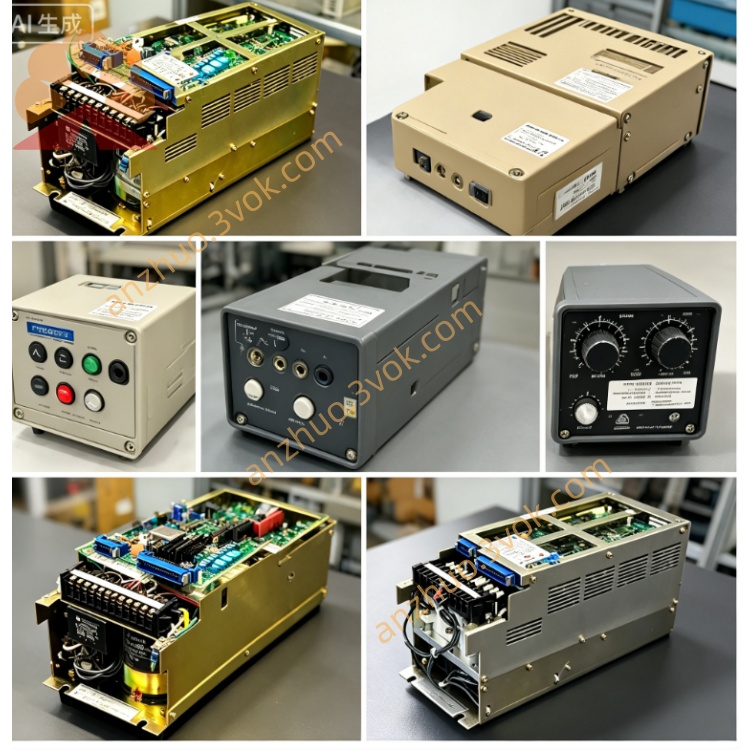
Yaskawa CACR‑SR15SZ1SS
CACR‑SR15SZ1SS is a 1.5 kW AC servo drive (SERVOPACK) from Yaskawa’s legacy VS‑800 (CACR‑SR) series, designed for three‑phase 200–230 VAC systems. It is a standard OEM model with special hardware and serial encoder interface, intended for machine tools, CNC equipment, and general automation applications requiring precise speed, position, or torque control. This model is discontinued; only tested used or refurbished units are available for maintenance and replacement.
Description
1.1 Overview
CACR‑SR15SZ1SS is a 1.5 kW AC servo drive (SERVOPACK) from Yaskawa’s legacy VS‑800 (CACR‑SR) series, designed for three‑phase 200–230 VAC systems. It is a standard OEM model with special hardware and serial encoder interface, intended for machine tools, CNC equipment, and general automation applications requiring precise speed, position, or torque control. This model is discontinued; only tested used or refurbished units are available for maintenance and replacement.
1.2 Model Number Definition
CACR stands for AC Servo Drive (SERVOPACK). SR indicates speed/position control on the VS‑800 platform. 15 denotes rated power of 1.5 kW. S means compatible with Yaskawa S‑series servo motors. Z refers to special hardware configuration with customized I/O and feedback circuits. 1 signifies single‑phase 200 VAC control power supply. S represents serial encoder interface. The final S indicates standard base firmware without special OEM parameter sets.
1.3 Applicable Motors
This drive is designed for Yaskawa S‑series servo motors equipped with serial encoders, rated for 200 VAC and 1.5 kW power class. It is not compatible with incremental encoder motors or non‑S‑series motors without hardware and firmware modifications.
2. Specifications
2.1 Electrical Ratings
Main power supply is three‑phase 200–230 VAC with tolerance of plus 10% to minus 15%, at 50 or 60 Hz. Control power supply is single‑phase 200–230 VAC with the same voltage tolerance and frequency range. Output power is 1.5 kW. Continuous output current is 9.9 A. Peak output current is 28 A for maximum 30 seconds. Output frequency ranges from 0 to 400 Hz. Encoder interface is serial, compliant with Yaskawa S‑series protocol.
2.2 Environmental Conditions
Operating ambient temperature is 0°C to +55°C. Storage temperature ranges from −20°C to +85°C. Humidity must be 90% RH or less, non‑condensing. Vibration resistance is 0.5 g from 10 Hz to 60 Hz, and 0.2 g from 60 Hz to 200 Hz. Altitude rating is up to 1,000 m above sea level; derate output by 1% per 100 m beyond 1,000 m.
2.3 Mechanical
Mounting orientation is vertical panel installation. Dimensions are 380 mm in height, 150 mm in width, and 200 mm in depth. Weight is approximately 5.5 kg. Cooling method is forced air with internal fan.
3. Features
Serial encoder support provides higher noise immunity, longer cable length up to 50 meters, and higher resolution compared to incremental encoders. Standard firmware configuration allows flexible parameter setup for various applications without pre‑set OEM profiles. Multi‑mode control includes analog speed or torque command via plus or minus 10 VDC signals, pulse‑direction position command using 5 V or 24 V pulses, and RS‑232C or RS‑485 serial communication with Modbus RTU protocol.
Built‑in protection functions include overcurrent, overvoltage, undervoltage, overtemperature, encoder failure, overload at 150% for 60 seconds, and regenerative circuit fault. Diagnostic seven‑segment LED display shows operational status and alarm codes for quick troubleshooting.
4. Installation and Wiring
4.1 Mounting
Install the drive vertically on a rigid, vibration‑free control panel. Maintain minimum 50 mm clearance above and below the unit for proper airflow and cooling. Do not install in direct sunlight, oily mist, dusty areas, or environments with corrosive gases. Ensure the mounting surface is flat and secure to prevent mechanical stress.
4.2 Main Circuit Wiring
Terminals R, S, T connect to three‑phase main power input of 200–230 VAC. Terminals L1 and L2 connect to single‑phase control power input of 200–230 VAC. Terminals U, V, W connect to the servo motor power terminals. Terminals P and B are for optional regenerative resistor connection. Terminal PE is protective earth for safety grounding.
4.3 Encoder Wiring
Connect the serial encoder cable to connector CN2, a 9‑pin D‑sub interface. Use shielded twisted‑pair cable and ground the shield only at the drive end to avoid ground loops. Maximum cable length for serial encoder connection is 50 meters. Ensure proper pin assignment and secure connector fastening.
4.4 Control I/O Wiring
Connector CN1 is a 50‑pin interface for control signals. Input signals include servo enable, forward run, reverse run, alarm reset, emergency stop, and position command pulses. Output signals include servo ready, alarm status, brake release, and speed reached. Analog signals include speed or torque command via plus or minus 10 VDC and speed monitor output via plus or minus 10 VDC.
5. Parameter Settings
5.1 Basic Parameters
Control mode is set via parameter Pn000, with 0 for speed control, 1 for position control, and 2 for torque control. Speed loop gain is adjusted via Pn100, with default value of 80. Speed loop integral time constant is set via Pn101, default 20 milliseconds. Position loop gain is adjusted via Pn200, default 100. Overload threshold is set via Pn300, default 150%.
5.2 Communication Parameters
Serial communication address is set via Pn500, ranging from 1 to 31 with default 1. Baud rate is configured via Pn501, default 9600 bps. Data format is 8N1, 8 data bits, no parity, 1 stop bit, set via Pn502.
6. Alarm Codes and Troubleshooting
Alarm code A.00 indicates normal operation with no fault. Alarm A.31 signifies overcurrent, caused by motor short circuit, wiring fault, or excessive gain settings; check motor and wiring, reduce gain values. Alarm A.40 indicates overtemperature, due to fan failure, poor ventilation, or continuous overload; clean fan, improve airflow, and check load conditions. Alarm A.51 denotes encoder error, resulting from cable break, encoder damage, or electrical noise; inspect encoder cable and connections, verify shielding. Alarm A.80 shows undervoltage, caused by power supply failure or voltage drop; check input power and wiring connections.
7. Maintenance
Daily maintenance includes checking LED display status, verifying cooling fan operation, and listening for unusual noise or vibration during operation. Monthly maintenance involves cleaning air vents and filters, tightening terminal block screws, and inspecting cables for damage or wear. Annual maintenance includes replacing cooling fan if worn, checking electrolytic capacitors for bulging or leakage, and verifying all electrical connections.
8. Compatibility Notes
CACR‑SR15SZ1SS shares identical hardware with other CACR‑SR15SZ1SD or SZ1SS models, but firmware and parameter settings differ by suffix code. It is interchangeable with other S‑series serial encoder drives of the same power rating with proper parameter adjustment. Replacement requires verification of motor encoder type, serial, and correct parameter configuration before operation.
9. Disclaimer
This document is an excerpt from the official Yaskawa CACR‑SR series user manual, Manual No. KG22E. For complete safety instructions, detailed wiring diagrams, full parameter lists, and comprehensive troubleshooting guidelines, refer to the original Yaskawa manual. Yaskawa Electric Corporation is not liable for any damage, injury, or loss resulting from improper installation, misuse, modification, or unauthorized operation of this product.
Get a Quote