
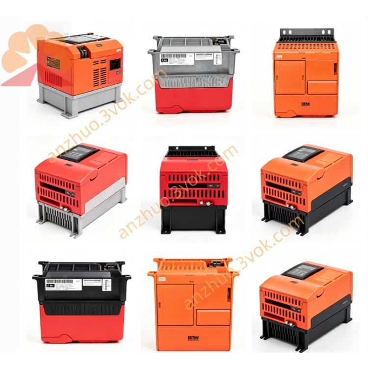
SEW MKS51A010-503 MOVIDYN Compact Servo Drive
Description
1. Product Overview
2. Model Code Explanation
MKS51A: MOVIDYN compact servo drive series
010: Rated output power 10 kW
503: 3-phase 380–500 V AC power class, standard version
3. Technical Specifications
3.1 Electrical Parameters
Input Voltage: 3×380–500 V AC (-10% / +10%), 50/60 Hz
Rated Output Current: 8.5 A
Rated Output Power: 10 kW (continuous mechanical power)
Internal Power Consumption: Approx. 40 W; standby power ≤ 60 W
Output Frequency Range: 0 – 400 Hz
Control Modes: Speed control, torque control, position control
Communication Interfaces: Ethernet (Modbus/TCP), RS-485; optional PROFIBUS and PROFINET
Safety Function: Optional STO (Safe Torque Off), compliant with PL d / SIL 2
Digital I/O: 8 digital inputs, 4 digital outputs (programmable)
3.2 Mechanical & Environmental Parameters
Protection Class: IP20 (cabinet installation only)
Cooling Method: Natural convection plus temperature-controlled fan (activates above 70% load)
Installation Type: 35 mm standard DIN rail mounting or wall mounting
Dimensions (W × H × D): Approx. 105 × 280 × 200 mm
Weight: Approx. 4.5 kg
Operating Temperature: 0 °C to +45 °C
Storage Temperature: -20 °C to +60 °C
4. Main Features
Compact integrated structure, saving installation space in control cabinets.
Advanced vector control ensures stable operation and high positioning accuracy.
LED indicators for power, running status and faults; physical buttons for start, stop and fault reset.
Support firmware update via USB or fieldbus.
Flexible programmable I/O for diverse on-site control requirements.
Standard industrial communication protocols for easy connection with PLC and upper control systems.
5. Typical Applications
Conveyor systems and packaging machinery
Machine tools and material handling equipment
Automated production lines and robotic units
6. Installation & Wiring
6.1 Mechanical Installation
Mount the drive on a rigid and vibration-free DIN rail or wall.
Keep a minimum clearance of 50 mm around the unit for heat dissipation.
Tighten mounting screws to a torque of 2.5 Nm.
6.2 Electrical Wiring
Power Terminals (L1, L2, L3, PE): Connect 3-phase main power supply and ensure reliable protective earth connection.
Motor Terminals (U, V, W, PE): Connect to the servo motor with shielded cables.
Communication Ports: Connect Ethernet or RS-485 interface to controller or commissioning PC.
STO Interface (Optional): Wire 24 V DC safety signal to the STO terminal.
6.3 EMC Requirements
Use shielded cables for power lines, motor lines and signal lines. Ground cable shields at both ends.
Separate power cables and signal cables with a distance of no less than 20 cm to avoid interference.
7. Commissioning & Operation
Pre-check all wiring, connections and insulation before power-on.
Switch on the main power; the status LED turns green for standby mode.
Complete parameter configuration, motor data setting and communication setup via SEW MOVITOOLS® software.
Perform trial run at low speed first, check for abnormal noise and vibration. Gradually increase speed and load to rated values.
Monitor operating temperature during operation; normal temperature shall not exceed 70 °C.
8. Maintenance
Conduct routine inspection every 6 months.
Clean dust on cooling vents and fan regularly.
Check tightness of all terminal connections and cable insulation.
Verify normal operation of the cooling fan.
9. Common Fault Diagnosis
F01 Overcurrent: Caused by short circuit, overload or motor failure. Check wiring and load condition.
F02 Overvoltage: Abnormal supply voltage or regenerative voltage surge.
F03 Overtemperature: Blocked ventilation or cooling fan malfunction.
F04 Communication Error: Damaged communication cable or inconsistent station address.
10. Storage & Disposal
Store the product in a dry and clean environment within the specified temperature range. Keep original packaging during storage.
Dispose of the product in accordance with local WEEE directives. Sort metal, plastic and electronic components separately for professional recycling.
Get a Quote