
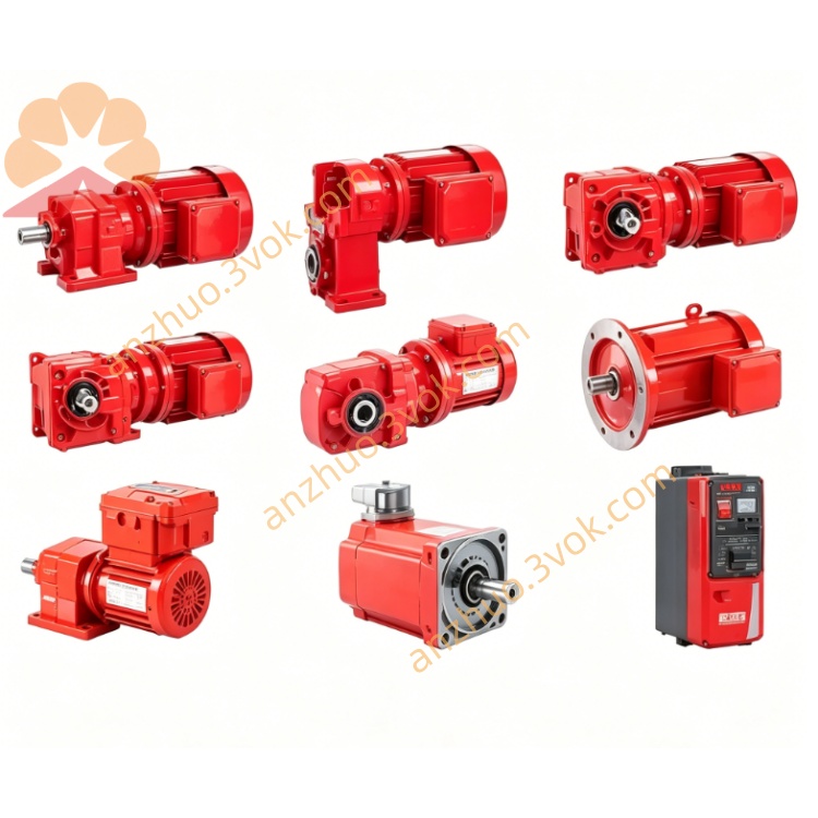
SEW MGFAS4-DSM-SNI-B MOVIGEAR Integrated Decentralized Drive
Description
1.1 Product Identification
Model: MGFAS4-DSM-SNI-B
Product Family: MOVIGEAR® (MGF)
Type: Decentralized Mechatronic Drive Unit (DSM)
Installation System: Single Line Network Installation (SNI)
Manufacturer: SEW‑EURODRIVE
1.2 Intended Use
This unit is a compact, decentralized drive integrating a gearbox, servo motor, and power electronics. It is designed for industrial automation applications (conveyors, packaging, material handling) and operates as part of a SNI system (one hybrid cable for power + communication).
1.3 Target Group
Qualified personnel trained in electrical/mechanical installation, startup, and maintenance of industrial drive systems.
1.4 Compliance & Standards
EN 61800‑5‑1 (Adjustable speed power drive systems)
EN 60204‑1 (Safety of machinery – Electrical equipment)
EN ISO 13849‑1 (Safety‑related control systems, PL d)
IEC 61508 (Functional safety, SIL 2)
2. Safety Instructions
2.1 General Warnings
High Voltage: Risk of electric shock. Disconnect power before maintenance; wait 5 minutes for capacitors to discharge.
Rotating Parts: Risk of entanglement. Secure output shaft against rotation during servicing.
Hot Surfaces: Housing may reach >80 °C during operation. Avoid contact.
Safety Integrity: STO (Safe Torque Off) is the only integrated safety function. For higher safety levels, use external safety controllers.
2.2 Installation Safety
Mount only on rigid, vibration‑free surfaces.
Use specified torque values for mounting screws.
Ensure IP65 protection is maintained (seals, cable glands, covers properly fitted).
2.3 Operation Safety
Do not operate without load or with blocked output shaft.
Avoid aggressive environments (corrosive gases, chemicals) unless optional HP200 surface protection is fitted.
3. Technical Specifications
3.1 Model Code Definition
MGFAS4: MOVIGEAR®, size 4, hollow shaft, 400 Nm torque class
DSM: Decentralized Servo Mechatronic
SNI: Single Line Network Installation
B: Standard design
3.2 Electrical Data
Input Voltage: 3×380–500 V AC (‑5% / +10%), 50/60 Hz
Rated Current: 3.46 A (at 2000 rpm)
Output Power: 4 kW (mechanical, continuous)
Efficiency Class: IE5 (ultra‑high efficiency)
Control Modes: Speed, position, vector control
Communication: SNI (PROFIBUS DP / PROFINET IO via hybrid cable)
Safety Input: STO (Safe Torque Off), PL d / SIL 2
3.3 Mechanical Data
Rated Torque: 400 Nm (continuous)
Motor Speed: 0–2000 rpm
Output Speed: 0.04–77.8 rpm (depending on gear ratio)
Gear Ratios: 5–2000 (customizable)
Output Shaft: Hollow shaft with keyway
Mounting: Torque arm (standard)
Protection Class: IP65 (dust‑tight, splash‑proof)
Temperature Range: ‑25 °C to +40 °C (operation)
Dimensions (W×H×D): ~220×160×80 mm
Weight: ~27 kg
3.4 Interfaces & Connections
SNI Hybrid Port: M23 connector (power + bus + 24 V DC)
I/O: 4 digital inputs / 2 digital outputs (via SNI)
STO: 2‑channel safety input (M12 connector)
Cable Glands: M16 (auxiliary), M23 (SNI)
4. Mechanical Installation
4.1 Mounting
Clean mounting surface; ensure flatness (≤0.5 mm/m).
Fit torque arm to unit and machine frame.
Align hollow shaft with driven shaft; use NOCO®‑Fluid on keyway.
Tighten mounting screws to 50 Nm (M8) / 120 Nm (M12).
Remove transport lock from breather valve before startup.
4.2 Shaft Connection
Hollow Shaft: Slide onto solid shaft; secure with set screw (30 Nm).
Keyway: Use standard parallel key; ensure no axial play.
5. Electrical Installation
5.1 SNI System Wiring
Hybrid Cable: Connect M23 SNI port to previous/next unit (daisy‑chain).
Cable Length: Max 100 m between units; total bus length ≤500 m.
Grounding: Connect unit housing to machine ground (PE) via low‑resistance path.
5.2 STO Connection
Wire 24 V DC safety signal to STO M12 connector (pins 1/2).
STO must be active (24 V) for operation; 0 V triggers safe torque off.
5.3 EMC Compliance
Use shielded hybrid cables; connect shield to housing at both ends.
Separate power and signal cables by ≥20 cm.
Avoid routing cables near high‑frequency sources (inverters, motors).
6. Startup & Commissioning
6.1 Pre‑Startup Check
Verify mechanical mounting (torque values, alignment).
Check electrical connections (SNI, STO, grounding).
Confirm no oil leaks (gearbox filled with FKM‑compatible oil).
6.2 Initialization
Apply 3×380–500 V AC and 24 V DC.
Unit powers up; LED indicator flashes green (standby).
Use SEW MOVITOOLS® software to:
Set node address (PROFIBUS/PROFINET).
Configure gear ratio, motor data, and control mode.
Test I/O and communication.
6.3 Test Run
Run at 10% speed for 5 minutes; check for unusual noise/vibration.
Gradually increase speed to 100%; monitor temperature (≤80 °C).
Verify STO function: Trigger STO; motor must coast to stop.
7. Operation
7.1 Normal Operation
LED Status:
Green (solid): Running normally.
Green (flashing): Standby.
Red (flashing): Fault (see Section 9).
Control: Operate via PLC (PROFIBUS/PROFINET) or local control (optional).
Load: Do not exceed 400 Nm continuous torque.
7.2 Operating Modes
Speed Mode: Set target speed via bus; unit maintains speed under load.
Position Mode: Execute positioning tasks (e.g., conveyor indexing).
Jog Mode: Manual speed control for setup.
8. Maintenance
8.1 Maintenance Schedule
Every 10,000 hours / 1 year:
Check gearbox oil level; replace if contaminated.
Inspect seals and cable glands for damage.
Tighten mounting and electrical connections.
Every 50,000 hours / 5 years:
Replace gearbox oil (SEW recommended type: FKM 150).
Inspect motor windings and bearings.
8.2 Oil Replacement
Disconnect power; wait 5 minutes.
Remove drain plug (bottom) and filler plug (top).
Drain old oil; refill with 1.2 L FKM 150 oil.
Replace plugs; check for leaks.
9. Fault Diagnosis
9.1 Common Faults
F01: Overcurrent: Short circuit or overload. Check wiring/load.
F02: Overvoltage: Supply voltage too high or regenerative overload.
F03: Overtemperature: Ambient too hot or fan blocked.
F04: STO Active: STO input triggered (safety stop).
F05: Communication Error: SNI cable fault or node address conflict.
9.2 Fault Reset
Clear fault via MOVITOOLS® or PLC command.
For persistent faults, power‑cycle the unit (disconnect 5 minutes).
10. Storage & Disposal
10.1 Storage
Store in dry, clean environment (‑20 °C to +40 °C).
Keep original packaging; avoid vibration and moisture.
Rotate output shaft monthly to prevent bearing damage.
10.2 Disposal
Dispose of according to local regulations (WEEE Directive).
Separate metal, plastic, and electronic components.
Gearbox oil is hazardous waste; dispose via licensed contractor.
11. Appendix
11.1 Spare Parts
Gearbox Oil: FKM 150 (1 L bottle)
Seal Kit: MGF4‑SEAL (includes oil seals, gaskets)
Fan: MGF4‑FAN (for high‑temp environments)
11.2 Contact
SEW‑EURODRIVE GmbH & Co KG Ernst‑Barkhausen‑Straße 1 76646 Bruchsal, Germany Phone: +49 7251 75‑0 Email: info@sew‑eurodrive.com Website: www.sew‑eurodrive.com
Get a Quote