
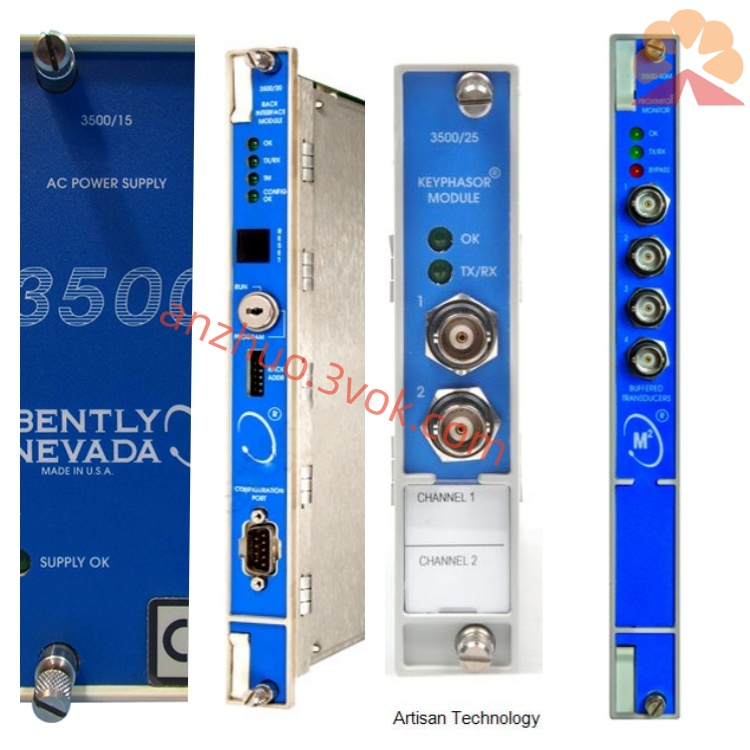
Bently Nevada 3300/40-03-01-01-00-00 System Power Supply Module
Description
Bentley 3300/40-03-01-01-00-00 Eccentric Monitoring Module Product Description
I. Product Overview
The Bentley 3300/40-03-01-01-00 is an eccentricity monitor module (Eccentricity Monitor) within the 3300 series TSI (Turbo Generator Instrumentation) of Baker Hughes (formerly GE Bentley Nevada), specifically designed for precise online monitoring of rotor deflection (eccentricity) in low-speed cranking (1–600 rpm) conditions of large steam turbines, gas turbines, generators, etc. It identifies rotor thermal or gravitational deflection and prevents severe accidents such as intense vibration, dynamic friction, and shaft system damage during the startup and speed-up process due to large shaft deflection.
The module is a 19-inch standard rack-mounted, hot-swappable design. It can be installed together with other modules of the 3300 series and shares the backplane - 24V DC power supply and system bus. It requires a 1 eccentric eddy current probe + 1 key phase signal for operation. It performs single-channel eccentric measurement and has built-in dual-level alarm relays, complying with API 670 standards. It is a key protection module during the startup phase of steam turbines.
II. Model Coding Rules (3300/40-AA-DD-BB-CC-EE)
3300: The 3300 modular TSI system by BENTLEY, with a unified rack, centralized power supply, and hot-swappable architecture.
40: Function code, rotor eccentricity monitoring module, for monitoring the rotor deflection during low-speed turning.
AA (Range / Measurement Range, 03 = ±10mil / ±0.254mm, Peak-Peak): 03 corresponds to ±10mil (±0.254mm) eccentricity range.
DD (Probe Sensitivity, 01 = 100mV/mil): Compatible with 11mm eddy current probe, standard sensitivity 100mV/mil.
BB (Relay Configuration, 01 = Dual Relays: Alert ALERT + Danger DANGER).
CC (Certification Level, 00 = General Industrial Certification).
EE (Safety Barrier / Explosion-proof, 00 = No Safety Barrier, applicable in non-explosion-proof areas).
III. Core Functions
1. Single-channel Eccentricity Measurement (for low-speed turning)
Input: 1 eccentric eddy current probe (for monitoring the rotor surface gap) + 1 key phase signal (Keyphasor, triggering phase reference).
Measurement Mode: Direct eccentric value (instantaneous value) + Peak-Peak (positive and negative extreme values of rotor deflection), accurately reflecting the degree of thermal deflection / gravitational deflection of the rotor.
Applicable Speed Range: 1–600rpm (low-speed turning), filtering out high-speed vibration interference, focusing on deflection monitoring.
Probe Compatibility: 3300 XL series 11mm eddy current probe, input impedance 10kΩ, -24V DC power supply.
2. High Precision Eccentricity Monitoring
Range: ±10mil (±0.254mm), Peak-Peak measurement.
Accuracy: ≤±0.1% of full scale (25℃), resolution 0.01mil.
Frequency Response: DC–1Hz, compatible with the slow bending change characteristics of low-speed turning.
Gap Voltage Monitoring: Real-time display of probe–rotor gap voltage, assisting in judging the probe installation status and signal quality.
3. Dual-stage Relay Alarm Output
Configuration of 2 epoxy resin sealed SPDT relays, each channel independent ALERT (warning) + DANGER (danger).
Contact Specifications: 250V AC/5A, 30V DC/5A, capable of driving audible and visual alarms, DCS/PLC or interlock circuits.
Threshold: Independent settings for positive and negative directions, adjustable delay 0–10 seconds, filtering out instantaneous fluctuations to avoid false alarms.
4. Front Panel Display and On-site Configuration
Display: LCD digital window + status LED, real-time display of eccentric peak-Peak / instantaneous value, gap voltage; OK/ALERT/DANGER/BYPASS four groups of LED, intuitively indicating running, alarm, bypass, and fault status.
Configuration: Key-based on-site programming, no need for a host computer to set range, alarm threshold, delay, probe calibration parameters, key phase trigger threshold.
5. Isolated Buffered Signal Output
1 isolated analog output (4–20mA or 0–10V selectable), electrical isolation ≥2500V AC from power supply and input signal.
Output Signal: Peak-Peak eccentricity, sent to the recorder, DCS, for trend analysis during startup process and fault traceability.
6. Comprehensive Self-Diagnosis and Fault Identification
24-hour Monitoring: probe break / short circuit, key phase signal abnormality, gap voltage over-limit, power supply abnormality, module hardware failure.
Distinguishing between real eccentricity anomalies and sensor / circuit faults, panel LED clearly indicates fault type, facilitating rapid troubleshooting.
7. System Integration and Anti-interference Metal shielding enclosure, input/output/power supply isolation ≥ 2500V AC, suitable for strong electromagnetic interference environments.
Compatible with 3300 series system bus (Type A), can be connected to the System 1 platform, enabling remote configuration, data storage, and trend analysis during the startup process.
IV. Technical Parameters
Measurement Parameters
Monitoring Channel: Single-channel eccentric measurement (with 1 eccentric probe + 1 key-phase probe).
Applicable Sensors: 3300 XL series 11mm eddy current probe (100mV/mil), Keyphasor key-phase probe.
Measurement Range: ±10mil (±0.254mm), peak-to-peak.
Measurement Accuracy: ≤ ±0.1% of full scale (25℃), resolution 0.01mil.
Frequency Response: DC–1Hz.
Input Impedance: Eccentric signal 10kΩ, key-phase signal 90kΩ.
Electrical Parameters
Power Supply: -24V DC (±10%), backplane power supply; supports short-circuit switching - 18V DC.
Power Consumption: Typical 1.5W, maximum ≤ 3W.
Relay Output: 2 SPDT (ALERT+DANGER), 250V AC/5A, 30V DC/5A.
Buffer Output: 1 isolated analog signal (4–20mA/0–10V selectable).
Isolation Strength: Input/output/power supply isolation ≥ 2500V AC.
Environmental and Mechanical Parameters
Operating Temperature: 0℃~+65℃ (standard type).
Storage Temperature: -40℃~+85℃.
Relative Humidity: 5%–95% (no condensation).
Installation Method: 19-inch standard rack slot, supports hot swapping.
Dimensions: 203mm (height) × 330mm (depth) × 51mm (width).
Weight: Approximately 1kg.
Protection Grade: IP20 (installed in control cabinet).
Certification and Compliance
Industry Standards: Compliant with API 670 Rotating Machinery Monitoring and Protection Standards.
Electromagnetic Compatibility: CE Certification, complies with EN 61000–6–2/4.
Safety and Environmental Protection: UL Certification, RoHS Compliance.
V. Typical Application Scenarios
Power Industry (thermal power / nuclear power turbine): Eccentric monitoring of rotor before impulse rotation, real-time tracking of rotor thermal bending / gravitational bending, eccentric over-limit alarm, prohibiting blind speed increase, avoiding large shaft bending, vibration exceeding standards, ensuring safe startup.
Petrochemical Industry (large process turbines): Eccentric monitoring of rotor during turbine shutdown after turning, identifying thermal deformation, preventing damage to the shaft system during restart, suitable for high-temperature, high-pressure conditions.
Metallurgical Industry (large transmission turbines): Eccentric monitoring of rotor during turbine turning state, dual-level alarm linkage for startup interlock, reducing equipment failure shutdown risks.
VI. Installation and Maintenance Specifications
Installation Requirements
Rack Installation: Push smoothly into the vacant slot of the 3300 rack, ensure that the rear connector is fully engaged, and tighten the panel screws.
Probe Wiring: Connect eccentric probe and key-phase probe according to the markings, single-ended grounding of the shielding layer; ensure a minimum duty cycle of 5% for the key-phase signal.
Alarm Wiring: Distinguish ALERT and DANGER contacts, connect to the alarm/interlock circuit, confirm correct logic.
Power-on Configuration: Set range (±10mil), alarm threshold (e.g. ALERT=5mil, DANGER=8mil), key-phase trigger threshold, and save.
Probe Installation: Align eccentric probe with the rotor journal, control the installation gap within 4mm linear zone; align key-phase probe with the rotor key slot / protrusion, ensure reliable triggering.
Daily Maintenance Inspection: Observe the eccentric value of the panel, the gap voltage and the LED status, and confirm that there are no fault alarms; Check that the terminals are not loose or oxidized.
Calibration: Every year, use a standard displacement generator to calibrate the eccentric accuracy and verify the accuracy of key phase triggering.
Cleaning: Regularly clean the dust on the module to ensure ventilation and heat dissipation.
Replacement of spare parts: When the module or probe is damaged, select the original Bentley component of the same model.
VIII. Usage Notes
This model is not explosion-proof. Installation is strictly prohibited in flammable and explosive hazardous areas.
It must be paired with the original Bentley 11mm eccentric probe + Keyphasor phase detection probe. Other specifications must not be used interchangeably.
It is only applicable for low-speed crankshaft rotation (1–600 rpm). High-speed vibration monitoring requires a vibration module (such as 3300/15) to be used in combination.
It is strictly prohibited to disassemble the module, modify the internal circuitry, and any illegal operation will result in the invalidation of the warranty.
Before wiring and maintenance, the power supply of the frame must be cut off to prevent short circuits and electric shock.
Get a Quote