
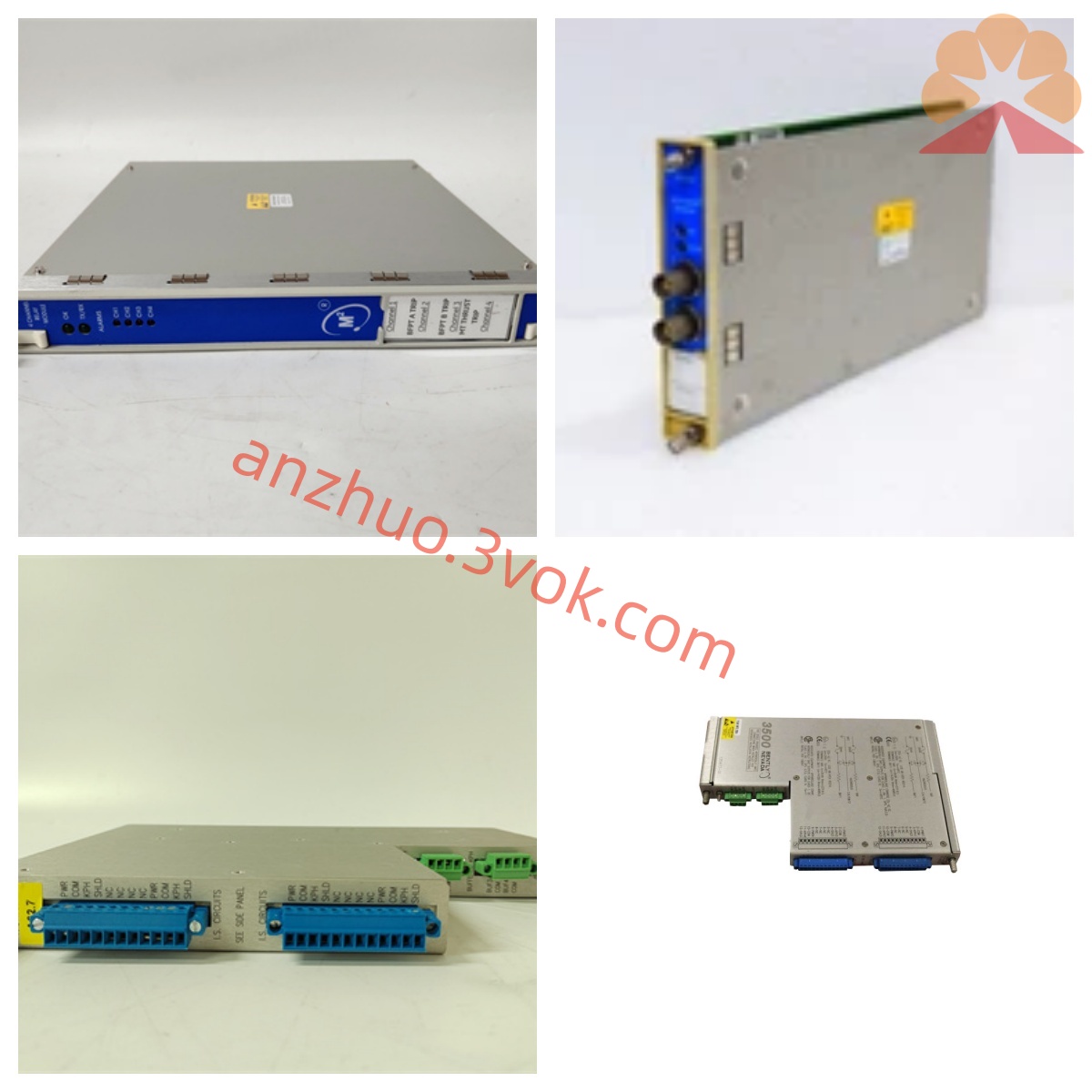
Bently Nevada 3300/35-02-02-01-00-00 Dual Channel Temperature Monitor Module
Description
Bentley 3300/35-02-02-01-00-00 Six-channel K-type Thermocouple Temperature Monitoring Module Detailed Product Description
I. Product Overview
The Bentley 3300/35-02-02-01-00-00 is a six-channel K-type thermocouple temperature monitoring module of the 3300 series TSI (Turbo Generator Monitoring Instrument) system developed by Baker Hughes (formerly GE Bentley Nevada). It is specifically designed for high-precision temperature monitoring and over-limit protection of high-temperature measurement points in large rotating machinery (such as steam turbines, gas turbines, generators, compressors, etc.) in industries such as thermal power, nuclear power, petrochemicals, and metallurgy. The module adopts a 19-inch standard rack structure, supports hot-swapping, and can be mixed with other monitoring modules of the 3300 series to share the backplane - 24V DC power supply and system bus; it is compatible with K-type thermocouples, with a measurement range of 0–1200°C, providing six independent temperature measurements, dual-level alarm relay outputs, no analog output, and complete self-diagnosis functions, in accordance with API 670 standards. It is the core equipment for monitoring and fault protection of rotating machinery in high-temperature conditions.
II. Model Coding Rules (3300/35-AA-BB-CC-DD-EE)
3300: Bentley 3300 modular TSI system, unified rack, centralized power supply, hot-swappable architecture.
35: Function code, representing a six-channel temperature monitoring module, independently monitoring 6 temperature signals.
02: Range code, corresponding to **0–1200°C** measurement range, suitable for K-type thermocouples in the high-temperature section, covering high-temperature measurement points such as steam turbine casings, exhaust, gas turbine combustion chambers, etc.
02: Sensor type code, suitable for K-type thermocouples (TC), an industrial general-purpose high-temperature thermocouple configuration.
01: Relay configuration code, equipped with two SPST non-sealed alarm relays, suitable for conventional industrial environment alarms and interlock circuits.
00: Output configuration code, no analog output, only retaining relay alarm and system bus communication functions.
00: Certification level code, representing general industrial-level certification, suitable for conventional industrial environments.
III. Core Functions
1. Six-channel high-precision K-type thermocouple temperature measurement
Independent 6 channels of thermocouple input, each channel compatible with K-type thermocouples (nickel-chromium - nickel-silicon), measurement range 0–1200°C, covering normal operation and abnormal overheating intervals of rotating machinery. Adopting high-precision built-in automatic cold junction compensation circuit (compensation range 0–50°C) and signal conditioning technology, measurement accuracy ≤ ±0.5°C (25°C reference point), resolution 0.1°C, capable of accurately capturing minute temperature changes in the high-temperature section. Real-time monitoring of thermocouple circuit status, early warning of wire breakage, short circuit, incorrect wiring, mismatch or damage of compensation wires, etc., suitable for complex industrial environments with strong electromagnetic interference and severe vibration.
2. Dual-level alarm and non-sealed relay output
Each channel independently configured **alert (ALERT), danger (DANGER)** two-level alarm thresholds, can be locally configured on the panel or remotely set, suitable for different high-temperature protection requirements of different equipment. Equipped with 2 non-sealed SPST relays, contact specifications 250V AC/5A, 30V DC/5A, can directly drive audible and visual alarms, DCS/PLC interlock circuits or shutdown protection devices. Alarm delay 0–10 seconds adjustable, filtering instantaneous temperature fluctuations, avoiding false alarms; relay status and module operation status are linked, faults trigger alarms automatically, ensuring timely response to high-temperature abnormalities.
3. On-site display and convenient configuration The front panel is equipped with an LCD digital display window and multiple sets of status LED indicators, which can display the real-time temperature measurement values of 6 channels, the resistance of the thermocouple circuit, the alarm threshold, and the fault code. There are four sets of LEDs: OK, ALERT, DANGER, and BYPASS, corresponding to normal operation, warning alarm, danger alarm, and module bypass status respectively. The operation status is clearly visible. It supports on-site configuration via buttons, without the need for an upper computer to complete range calibration, thermocouple type matching, cold end compensation on/off, alarm threshold configuration, delay parameter adjustment, and loop diagnosis settings. The debugging is efficient and convenient, reducing the difficulty of on-site maintenance.
4. No analog output, focused on alarm protection
This model has no independent analog output function. The core focuses on temperature monitoring + dual-level alarm protection, simplifying the circuit design and improving the anti-interference ability and operational stability. Through the 3300 series system bus, the real-time data of 6 temperature channels, alarm status, and fault information can be uploaded to the BTL System 1 platform for remote monitoring and data management, meeting basic monitoring and protection requirements, and suitable for scenarios without local analog signal connection.
5. Comprehensive self-diagnosis and fault identification
It continuously monitors the module's own hardware, thermocouple circuit, cold end compensation status, power supply status, and signal integrity without interruption. It can accurately identify issues such as thermocouple breakage / short circuit, compensation wire errors, cold end compensation anomalies, power fluctuations, module circuit faults, etc. It distinguishes between real temperature anomalies and sensor / circuit faults. The panel LEDs clearly indicate the fault type, and in conjunction with on-site display of fault codes, it facilitates rapid troubleshooting and maintenance, reducing the risk of unplanned shutdown due to high-temperature faults.
6. System integration and strong anti-interference capability
The metal shielding shell design, multiple electrical isolation between input, output, and power supply circuits, is suitable for industrial environments with strong electromagnetic interference and high vibration such as thermal power, nuclear power, and petrochemicals. It is compatible with the 3300 series system bus (type A), and can be connected to the BTL System 1 equipment status monitoring platform to achieve remote configuration, real-time data transmission, historical trend query, fault warning analysis, etc., integrating into the enterprise equipment management system. It supports interfacing with third-party systems such as DCS and PLC through bus protocol to meet factory automation integration requirements, ensuring stable transmission of temperature monitoring data.
Four. Detailed technical parameters
Measurement parameters
Monitoring channels: 6 independent temperature measurements (compatible with K-type thermocouples)
Sensor type: K-type thermocouple (nickel-chromium - nickel-silicon)
Measurement range: 0–1200℃
Measurement accuracy: ≤±0.5℃ (25℃ reference point, typical value)
Resolution: 0.1℃
Cold end compensation: Built-in automatic cold end compensation, compensation range 0–50℃
Response time: ≤5 seconds (reaching 90% stable reading)
Input impedance: ≥10MΩ (per channel)
Electrical parameters
Working power supply: -24V DC (±10%), backplane power supply; supports short-circuit switching - 18V DC
Power consumption: typical 2.8W, maximum ≤4.5W
Relay output: 2 SPST (ALERT+DANGER), non-sealed, 250V AC/5A, 30V DC/5A
Analog output: None
Isolation strength: Input / power supply ≥2500V AC
Sensor power supply: No external power supply required, thermocouple self-generated signal input
Environmental and mechanical parameters
Working temperature: 0℃~+65℃ (standard industrial grade)
Storage temperature: -40℃~+85℃
Relative humidity: 5%–95% (no condensation)
Vibration tolerance: Complies with IEC 60068-2 standard, anti-vibration, anti-shock Installation method: 19-inch standard rack slot, supports hot swapping
Dimensions: 203mm (height) × 330mm (depth) × 51mm (width)
Weight: Approximately 1.3kg
Protection level: IP20 (suitable for installation in control cabinets)
Certifications and compliance
Industry standards: Compliant with API 670 Rotating Machinery Monitoring and Protection Standards
Electromagnetic compatibility: CE certification, complies with EN 61000-6-2/4
Safety certification: UL certification
Environmental compliance: RoHS Directive compliance
V. Typical application scenarios
Power industry (thermal power / nuclear power turbine / gas turbine): Multi-point monitoring of turbine cylinder temperature, exhaust temperature, gas turbine combustion chamber temperature, exhaust gas temperature, prevent overheating-induced material aging, component deformation, equipment damage; full-stage high-temperature protection during startup acceleration, normal operation, shutdown rotation, triggered by overheating and generating alarms or interlock shutdown to ensure safe and stable operation of the unit.
Petrochemical industry (large cracking turbines / process heating furnaces): Synchronous monitoring of turbine high-temperature bearing temperature, sealing chamber temperature, heating furnace outlet temperature, reaction medium temperature, suitable for high-temperature, high-pressure, and highly corrosive industrial environments, prevent equipment burnout, medium cracking, and safety accidents caused by overheating, ensure continuous industrial production.
Metallurgical industry (large heating furnaces / sintering machines / high-temperature fans): Batch monitoring of furnace internal temperature, flue gas temperature, equipment high-temperature shell temperature, winding temperature, dual-level alarm linkage with equipment operation interlock, timely warning of overheating faults, reduce unplanned shutdown risks, ensure stable and efficient operation of the metallurgical process.
VI. Installation and commissioning specifications
Installation requirements
Rack installation: Push smoothly into the vacant slot of the 3300 series rack, ensure that the rear connectors are fully engaged, tighten the panel fixing screws to avoid loosening and contact failure; reserve ventilation space at the installation location to avoid heat accumulation affecting module heat dissipation.
Sensor wiring: K-type thermocouple uses positive and negative pole separation wiring (positive pole nickel chromium, negative pole nickel silicon), equipped with dedicated K-type compensating cables, select high-temperature-resistant shielded cables, single-ended grounding (on the control cabinet side), avoid circulating interference; during wiring, avoid bending or pulling the cables, prevent breakage or signal attenuation.
Alarm wiring: Distinguish ALERT and DANGER relay contacts, connect to the alarm/interlock circuit, confirm that the wiring is firm and there is no short-circuit hazard, ensure reliable output of alarm signals.
Sensor installation: Thermocouple probe is tightly attached to the high-temperature surface of the measured equipment, fixed using a high-temperature clamp, ensure accurate temperature measurement; fix the probe cable firmly to avoid vibration wear or cable breakage, keep away from strong electromagnetic radiation sources.
Commissioning steps
Power-on self-check: The module powers on and automatically performs self-check, the OK light is constantly on indicating normal hardware, when the fault light is on, check the wiring, sensors, or hardware issues.
Sensor calibration: Enter calibration mode through the panel buttons, select K-type thermocouple type, enable automatic cold junction compensation, calibrate the circuit resistance parameters to ensure temperature measurement accuracy.
Alarm settings: According to the equipment operation standards, set warning thresholds (such as 800°C) and danger thresholds (such as 1000°C), adjust alarm delay (such as 2 seconds), save parameters.
Signal verification: During equipment operation, observe whether the 6-channel temperature values on the panel are stable, without jumps, drifts; check that there are no fault indications in the thermocouple circuit, confirm that the alarm function is normal before putting it into operation.
VII. Maintenance and fault troubleshooting
Daily maintenance
Regular inspection: Daily observation of panel temperature values, circuit status, and LED status, confirm no alarms or fault indications; check that the terminal connections of the module are not loose or oxidized, and the rack ventilation and heat dissipation are good. Annual Calibration: Use standard thermocouples to calibrate the temperature measurement accuracy, verify the alarm action values and delay accuracy of relays, and ensure the reliability of monitoring and protection functions.
Cleaning and Protection: Regularly clean the dust on the module surface with a dry soft cloth to prevent dust accumulation from affecting heat dissipation; strictly prohibit liquids and metal debris from entering the module interior to prevent short-circuit faults.
Common Fault Troubleshooting
OK light goes out (module failure): Check if the backplane power supply is normal (-24V DC), reinsert and re-examine the module; if still abnormal, replace the module.
Abnormal temperature display (jumping / drift): Check if the K-type thermocouple wiring is loose, wrongly connected, or broken, and if the compensation wires are matched, damaged, and rewire or replace the sensor; check if the environmental temperature is beyond the working range and if there is strong electromagnetic interference.
No temperature display: Check if the thermocouple is damaged, if the positive and negative poles are connected reversely, if the compensation wires are open-circuited, and troubleshoot and replace the faulty components.
Alarm mis-trigger: Re-calibrate the alarm threshold and delay parameters, check if the cold junction compensation is abnormal, and optimize the installation and wiring shielding measures of the sensor.
VIII. Usage Notes
This model is of non-explosion-proof design. Installation and use are strictly prohibited in flammable and explosive hazardous areas.
It must be equipped with **K-type thermocouple (nickel-chromium - nickel-silicon)** temperature sensor and dedicated K-type compensation wires. Mixing with other types of thermocouples (such as S-type, B-type) or RTD is not allowed; otherwise, it will cause measurement errors or equipment damage.
It is only applicable for temperature monitoring within 0–1200℃. For over-temperature scenarios, select the corresponding range module.
Do not disassemble the module, modify the internal circuitry, or replace non-original accessories without authorization. Illegal operations will result in the invalidation of equipment warranty and may cause safety hazards.
Before connecting or inspecting the module, cut off the main power supply of the frame to prevent short circuits and electric shock accidents; do not plug or unplug the module while it is powered on.
When the module is in a long-term shutdown state, it is recommended to remove the module from the frame, store it in a dry and cool environment to avoid moisture and dust affecting performance.
Get a Quote