
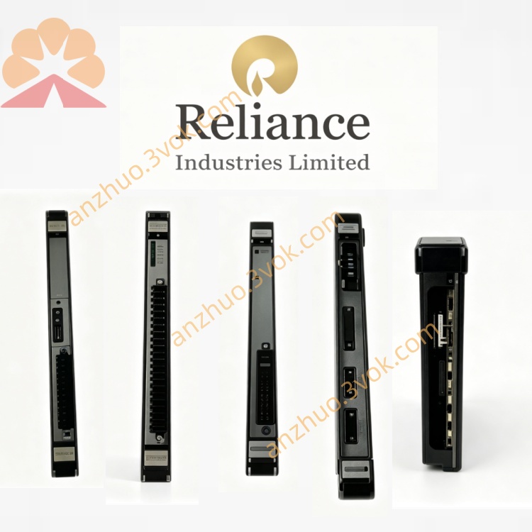
Reliance 24C4140U
Description
Product Description
Model Number Definition
24: Indicates 24 VDC control logic compatibility.
C: Series code for control/interface modules (Reliance Electric standard).
4140: Core functional code: 41 = DC bus monitoring, 40 = 40 HP power range compatibility.
U: Suffix for universal or updated version, denoting revised circuitry for wider drive compatibility.
Technical Specifications
Control Voltage: 24 VDC ±10%
DC Bus Monitoring Range: 0–800 VDC
Brake Current Monitoring: 0–50 ADC
Switched Output Rating: 24 VDC / 1 A (transistor, non-contact)
Operating Temperature: -10°C to +60°C
Storage Temperature: -40°C to +85°C
Enclosure Rating: NEMA 1 (IP20), panel-mount
Weight: ~0.88 kg
Certifications: UL recognized, RoHS compliant
Interface & Communication Configuration
Power Terminals: 24 VDC (±), DC Bus (+/−), Brake Current Sense
Control Outputs: S1-2 (switched transistor output, terminals 1=−, 2=+)
Status Indicators:
Left LED: ON when DC bus voltage > 50 VDC
Right LED: ON when braking current (IB) > 0
Communication: No direct fieldbus; hardwired I/O for drive interlock and brake control
Core Functions
DC Bus Voltage Monitoring: Continuously tracks DC bus level; triggers status LED at >50 VDC
Brake Current Detection: Monitors braking current; activates right LED during regeneration
Smart Brake Control: Transistor switch S1-2 closes when DC bus >50 V and IB=0; opens during braking or low bus voltage
Isolation & Protection: Electrical isolation between high-voltage DC bus and low-voltage control circuits
System Interlock: Provides dry-contact equivalent signal for drive enable/interlock logic
Application Scenarios
Reliance GV3000/FlexPak Drives: 20–50 HP AC drives (380–460 VAC)
Industrial Motion Control: Conveyors, cranes, hoists requiring dynamic braking
Process Industry: Pumps, fans, extruders with regenerative loads
Legacy System Retrofits: Replacement for aged brake control modules in existing installations
High-Power Drive Maintenance: Critical spare for minimizing downtime in manufacturing
Usage & Maintenance Instructions
Installation: Mount vertically on DIN rail or panel; allow 50 mm clearance for ventilation. Torque terminals to 1.2–1.5 Nm.
Wiring: Use shielded cables for DC bus and brake signals; separate from AC power wiring by ≥100 mm.
Operation: Verify LED status after power-up: left LED ON (bus charged), right LED OFF (no braking).
Maintenance: Inspect terminals quarterly for tightness/corrosion; clean housing annually with dry cloth.
Safety: Disconnect all power (AC and DC) before maintenance; wait 5 minutes for DC bus discharge.
Get a Quote