
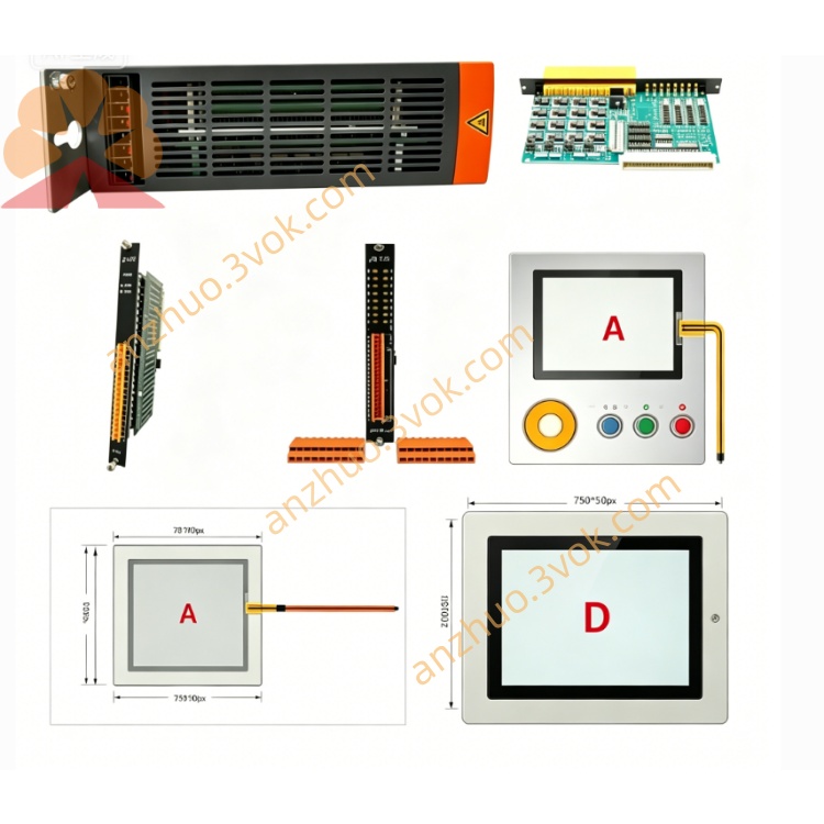
B&R 3IF787.9-1 Network and Fieldbus Module
Description
B&R 3IF787.9-1 Network and Fieldbus Module Detailed Product Description
I. Basic Information
B&R 3IF787.9-1 is an aPCI dual-protocol network and fieldbus module specially designed by Austria B&R for the 2005 system and the Automation PC platform. It integrates 1 POWERLINK real-time Ethernet bus and 1 CAN fieldbus, capable of simultaneously handling high-speed real-time network communication and traditional fieldbus control tasks, achieving heterogeneous network interconnection and protocol conversion. It is suitable for installation in aPCI slots in control cabinets and is widely used in motion control, distributed I/O, old equipment networking, and multi-bus mixed networking scenarios. It is the core communication component connecting real-time industrial networks and traditional fieldbuses.
II. Core Technical Parameters
(1) Hardware Interfaces
POWERLINK Interface (IF2): Type 3 interface, compatible with POWERLINK V1/V2 versions, configurable as a master (management node) or slave (controlled node), standard RJ45 connector, transmission rate 100 Mbps, maximum transmission distance of 100 meters per segment, suitable for high-speed real-time motion control networks.
CAN Bus Interface (IF1): 4-pin male connector, supports CAN 2.0A/B protocols, maximum transmission rate 500 kbps, maximum communication distance 1000 meters at 125 kbps rate, built-in bidirectional object buffer, supports multi-node networking, requires separate purchase of terminal block TB704 for wiring.
System Bus Interface: Standard aPCI bus, compatible with B&R 2005 series CPUs, Automation PC 910 and other devices, powered directly by the slot, no need for additional external power adapter.
Electrical Isolation: POWERLINK Interface, CAN Bus Interface and system side are completely electrically isolated, isolation voltage 2500V AC, effectively suppressing common-mode interference, surge voltage and electromagnetic interference, ensuring stable communication in harsh environments.
(2) Electrical Characteristics
Power Supply Voltage: 3.3V DC ±10%, 5V DC ±10%, powered by the aPCI slot, no need for additional power adapter.
Power Consumption: Typical 2.5W on 3.3V side, typical 0.5W on 5V side, total typical power consumption 3.0W; typical working current on 3.3V side 750mA, typical working current on 5V side 100mA, low power consumption design suitable for compact power supply environments in cabinets, reducing heat dissipation pressure.
Anti-interference Capability: Compliant with IEC 61000-6-2/4 industrial electromagnetic compatibility standards, capable of withstanding strong electromagnetic interference from inverter, large power motors, etc.
(3) Environmental Adaptability
Operating Temperature: 0℃ to + 60℃ (horizontal standard installation), suitable for conventional industrial sites; vertical installation or high-load scenarios require reduced environmental temperature usage.
Storage Temperature: -25℃ to + 70℃, meets long-term storage, transportation and idle standby requirements.
Relative Humidity: 5% to 95%, no condensation, avoiding short circuits or corrosion in humid environments.
Protection Grade: IP20, dustproof and solid foreign object protection, suitable for clean and dry installation environments in control cabinets, not directly exposed to outdoor or dust, water vapor severe areas.
Vibration and Impact Resistance: Compliant with IEC 60068-2-6 (vibration), IEC 60068-2-27 (impact) standards, can withstand regular mechanical vibration and impact in industrial sites, long-term operation not prone to loosening or failure.
(4) Performance Indicators POWERLINK Performance: The master station mode supports up to 32 slave stations, with the shortest bus cycle being 100 μs. It supports hard real-time data transmission, meeting the requirements for multi-axis servo synchronization and high-precision motion control. The slave station mode supports high-speed real-time response, and is compatible with servo drives and remote I/O devices for connection.
CAN Bus Performance: It supports the CANopen protocol, can connect CANopen slave station devices (such as sensors, actuators, frequency converters), supports NMT network management, PDO process data, and SDO service data transmission. Node IDs can be configured, and the networking is flexible.
Protocol Support: Fully supports POWERLINK (V1/V2), CAN 2.0A/B, CANopen, and is compatible with TCP/IP basic network protocols, enabling data interaction and protocol conversion between POWERLINK and CAN bus.
System Compatibility: Fully compatible with the Beckhoff Automation Studio development environment, supporting module parameter configuration, communication protocol settings, remote diagnosis, and firmware online upgrade, and seamlessly compatible with the 2005 system and the Automation PC ecosystem.
III. Core Functions
(1) POWERLINK Real-time Ethernet Communication
As a high-speed real-time network interface, it can be configured as a POWERLINK master station or slave station. In the master station mode, it manages the real-time motion network, connects servo drives, encoders, machine vision equipment, and realizes multi-axis synchronization control and high-speed data transmission; in the slave station mode, it connects to the superior POWERLINK network, expands the system's real-time control nodes, with the bus cycle being the shortest 100 μs, ensuring hard real-time communication.
(2) CAN Field Bus and CANopen Device Interconnection
Integrated CAN field bus interface, supports CAN 2.0A/B and CANopen protocols, can directly connect CANopen slave station devices, such as field sensors, temperature instruments, pressure transmitters, frequency converters, remote I/O modules, etc., achieving seamless connection between traditional field bus devices and the Beckhoff real-time control system, compatible with the upgrading scenarios of old CAN devices.
(3) Dual Bus Data Bridging and Protocol Conversion
Core implementation of data intercommunication between POWERLINK real-time Ethernet and CAN field bus, supports bidirectional data mapping and forwarding, can convert POWERLINK high-speed control data to CAN bus data, or vice versa, solving the problems of interconnection between new and old devices and different bus networks, simplifying the integration architecture of heterogeneous systems, and reducing the cost of renovation.
(4) Bus Diagnosis and Status Monitoring
The module is equipped with multiple LED status indicators, which can display the power supply status of the module, the connection / data transmission status of the POWERLINK port, the communication status of the CAN bus, and the fault alarm status in real time; in conjunction with the Automation Studio software, it can achieve remote diagnosis, online status monitoring of nodes, analysis of communication load rate, fault location and log recording, providing early warnings of risks such as bus overload and link failure, and reducing maintenance difficulty.
(5) Hot Swap and Flexible System Expansion
Compatible with the hot swap function of the Beckhoff 2005 system, it can be plugged in and replaced modules without stopping the controller or system operation, significantly reducing maintenance downtime; through the aPCI slot, multiple modules can be installed in parallel, flexibly expanding the number of POWERLINK and CAN bus interfaces, adapting to the expansion requirements of different-scale automation systems.
(6) Network Management and Data Buffering Area Built-in bidirectional object buffer for data transmission and reception, supporting data caching and forwarding for POWERLINK and CAN bus, preventing data loss; supporting CANopen NMT network management, configurable node ID, baud rate, and PDO mapping parameters, suitable for different networking requirements of CAN devices; POWERLINK supports network topology management, ensuring stable real-time network operation.
IV. Product Features
Dual-bus integrated design: Integrates POWERLINK real-time Ethernet and CAN fieldbus interfaces in one module, one module covers both high-speed real-time control and traditional fieldbus communication, simplifies hardware configuration, and reduces networking costs.
Industrial-grade high reliability: Uses industrial-grade components, fanless cooling design, wide temperature working range, strong electromagnetic interference resistance, suitable for harsh industrial environments with dust, vibration, and strong electromagnetic interference, ensuring stable and reliable operation over the long term.
Hard real-time and compatibility: POWERLINK bus supports microsecond-level communication cycles, hard real-time transmission characteristics meet the requirements of multi-axis synchronization and high-precision motion control; at the same time, it is compatible with CANopen legacy devices, suitable for upgrading scenarios of new and old systems.
Compact modular design: Standard aPCI size, small in volume, can be directly fixedly installed by inserting into the aPCI slot in the control cabinet, occupies little space, suitable for the limited space layout of the control cabinet, installation is convenient and efficient.
Protocol conversion and easy maintenance: Native support for POWERLINK and CAN bus protocol conversion, achieving interconnection of heterogeneous networks; LED status indication + remote software diagnosis dual guarantee, quickly locate faults; supports hot swapping, maintenance does not require downtime, reducing operation and maintenance costs.
Beckhoff ecosystem seamless compatibility: Fully compatible with Beckhoff 2005 system, Automation PC, and Automation Studio development environment, unified configuration, programming, and maintenance, supports firmware online upgrade, strong compatibility, and good scalability.
Global certification compliance: Certified by CE, UKCA, KC, cULus HazLoc, etc., compliant with industrial safety and electromagnetic compatibility standards, suitable for industrial sites worldwide, strong compliance.
V. Application Scenarios
Motion control system expansion: As a POWERLINK slave or master station, connect servo drives, encoders, build a multi-axis motion control network, and access auxiliary sensors, actuators through CAN bus to achieve high-precision synchronous control and auxiliary equipment linkage, suitable for robots, CNC machines, packaging machinery, etc.
Renovation of old CAN devices networking: Connect traditional CANopen sensors, frequency converters, remote I/O modules to the Beckhoff POWERLINK real-time control system, achieve data communication between new and old devices, no need to replace existing CAN devices, reducing upgrading costs.
Distributed I/O mixed networking: Connect high-speed remote I/O through POWERLINK, connect low-speed field I/O through CAN bus, build a hierarchical distributed control system, balance high-speed control and low-cost on-site signal acquisition, suitable for intelligent manufacturing production lines, intelligent warehouse logistics, etc.
Multi-bus protocol conversion gateway: As a protocol conversion gateway for POWERLINK real-time Ethernet and CAN fieldbus, realize data interaction between two heterogeneous networks, suitable for automation systems with mixed use of multiple brands and multiple protocols, solving the problem of device interconnection. Special industrial control scenarios: Suitable for industries such as metallurgy, power, chemical engineering, and rail transportation. It can operate stably in strong electromagnetic interference and wide temperature environments, ensuring reliable transmission of real-time control signals and fieldbus data, and guaranteeing safe and stable production.
VII. Installation and Usage Precautions
Installation environment requirements: The module should be installed in a sealed control cabinet, maintaining internal ventilation, dryness, cleanliness, and dust-free; the environmental temperature should be controlled between 0℃ and + 60℃, avoiding dampness, corrosive gases, strong heat sources, frequency converters, and large power motors as strong electromagnetic interference sources, to prevent interference stability and module lifespan from being affected.
Installation operation norms: Before installation, the power supply of the controller and control cabinet must be cut off to prevent module damage caused by live operation; align the module with the aPCI slot and push it in smoothly to ensure that the gold fingers fully contact the slot without any deviation or looseness; tighten the module fixing screws; after installation, check if the module is firmly fixed without shaking; it is necessary to order the wiring terminal TB704 separately for CAN bus wiring.
Wiring and wiring requirements: The POWERLINK port uses standard shielded twisted-pair cables, the RJ45 interface should be firmly inserted, and the cable shielding layer should be grounded at one end; the CAN bus uses dedicated shielded bus cables, the 4-pin connector wiring should be standardized, avoiding parallel long-distance wiring and reducing electromagnetic interference; all wiring should be neat and orderly, with clear markings, facilitating later maintenance.
Parameter configuration and debugging: After power-on, the module can be identified through the Automation Studio software, configure the POWERLINK master/slave mode, IP address, bus cycle, configure the CAN bus baud rate, node ID, CANopen parameters (PDO mapping, NMT mode); after configuration, download the parameters to the module and restart the module to take effect; during the debugging stage, check the LED status indicator lights, monitor the communication status and bus load rate through the software, and troubleshoot communication faults.
Maintenance and care: Regularly (monthly) check if the module is firmly fixed, if the wiring is loose, if the LED status is normal, use a dry soft cloth to clean the module surface dust, to avoid dust accumulation affecting heat dissipation; avoid frequently plugging and unplugging the module to prevent gold finger wear and poor contact; firmware upgrades must be operated through the official Automation Studio software of B&R, during the upgrade process, it is strictly prohibited to cut off power, plug or unplug the module to prevent damage to the module firmware.
Fault handling prohibitions: When the LED fault indicator light alarms or the software diagnostic communication is abnormal, first check for loose wiring, baud rate/node ID conflicts, excessive bus load, network loops, etc., and gradually troubleshoot;严禁 plugging and unplugging the faulty module while powered on to prevent short circuits or electric shock hazards; when the fault cannot be resolved, contact the official support of B&R or authorized dealers, do not attempt to disassemble or repair the module by yourself to avoid damaging the module or expanding the fault range.
VII. Quality Assurance and After-sales
The B&R 3IF787.9-1 is an original B&R product. The product has a 12-month warranty period. Non-human damage and faults not caused by improper use during the warranty period can enjoy free repair or replacement services; global warranty services are supported, you can query product warranty information and apply for after-sales support through the B&R official website, customer service hotline or authorized dealers. At the same time, provide technical consultation, product selection guidance, remote debugging, on-site technical support and other supporting services to help users quickly complete module deployment, system debugging and daily maintenance, ensuring the stable operation of the automation system.
Get a Quote