
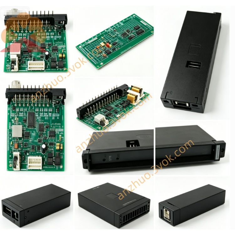
0-60044
Description
Model Number Definition
0‑: Standard Reliance board prefix60044: Series identifier (PMI Parallel Interface Module for DPS)
Technical Specifications
Module Type: Parallel Interface & Synchronization Module (PMI‑DPS)
Compatibility: AutoMax SA 3000/SA 3100 AC/DC drives (DPS architectures)
Interface: 4‑channel parallel I/O (TTL‑level, differential signaling)
Data Rate: 10 Mbps (synchronous, Manchester encoding)
Logic Voltage: +5V DC (backplane), ±12V DC (signal conditioning)
Isolation: 1500Vrms (channel‑to‑backplane)
Operating Temperature: 0 to 55°C
Storage Temperature: -20 to 70°C
Dimensions (W×H×D): ~30 × 220 × 180 mm (double‑wide slot)
Weight: ~1.6 kg
Mounting: Standard SA 3000/SA 3100 PMI rack slot
Status LEDs: 8 total (4 green: PWR, SYNC, ACT, LINK; 4 red: FLT1–FLT4)
Key Features:
Multi‑module synchronization (up to 8 parallel power modules)
Dynamic load sharing (current/voltage balancing across modules)
Fault aggregation (centralized monitoring of parallel module faults)
High‑noise immunity (differential signaling, EMI shielding)
Interface & Communication
Front Panel:
Parallel Port: 50‑pin high‑density D‑sub (shielded) for parallel module daisy‑chaining
LEDs:
PWR (green): On = +5V OK
SYNC (green): Blinking = Synchronization lock
ACT (green): Blinking = Data transmission activity
LINK (green): On = Parallel chain communication healthy
FLT1–FLT4 (red): On = Module‑specific fault (overcurrent, overtemperature, etc.)
Backplane Edge Connector:
Power: +5V, ±12V, GND
Control: PMI processor interface (fiber or backplane bus)
Data: Parallel control/feedback signals to power modules
Core Functions
Parallel Module Synchronization: Generates precision synchronization clocks to align switching cycles of up to 8 parallel power modules, ensuring phase‑perfect operation for high‑current output.
Dynamic Load Sharing: Monitors current/voltage across parallel modules and adjusts gate drive signals to balance load distribution, preventing overload of individual modules.
Fault Monitoring & Aggregation: Collects fault status from all connected parallel modules, provides centralized fault indication via front‑panel LEDs, and transmits fault data to the PMI processor for diagnostics.
High‑Speed Data Routing: Transmits real‑time control commands (from PMI processor) and feedback data (from power modules) between parallel chain and PMI backplane at 10 Mbps.
System Expansion: Enables scalable DPS architectures by allowing additional power modules to be added via daisy‑chaining, supporting high‑power applications (e.g., metal rolling, paper machines).
Applications
High‑Power DPS Drives: AutoMax SA 3000/SA 3100 systems with parallel‑connected power modules (AC/DC drives ≥ 500 kW).
Precision Load Sharing: Processes requiring balanced power distribution across multiple drive modules (e.g., large coil winding, extrusion lines).
Legacy System Expansion: Upgrading existing SA 3000/SA 3100 drives by adding parallel power modules without full system replacement.
High‑Current Industrial Drives: Heavy‑duty applications such as steel rolling mills, mine hoists, and large conveyor systems.
Usage & Maintenance
Installation
Power OFF only: Insert into designated PMI rack slot; secure with front‑panel screws. No hot‑swap.
Wire parallel modules to 50‑pin D‑sub using shielded twisted‑pair cable (Reliance‑specified pinout).
Configuration
Set drive parameters for parallel operation (number of modules, load‑sharing algorithm) via PMI software/keypad.
Calibrate synchronization offset for phase alignment (critical for high‑current stability).
Routine Maintenance
Every 3–6 months: Power off; clean dust from connectors/PCB; check D‑sub contacts and cable shielding.
Verify LEDs: PWR/SYNC/LINK ON, ACT blinking during normal operation; FLT LEDs OFF.
Troubleshooting
Load imbalance: Recalibrate load‑sharing parameters; check for loose cable connections.
Synchronization loss: Verify SYNC LED; check for EMI interference or faulty clock circuitry.
FLT LED on: Identify faulty module via LED mapping; inspect power module for overcurrent/overtemperature.
Get a Quote