
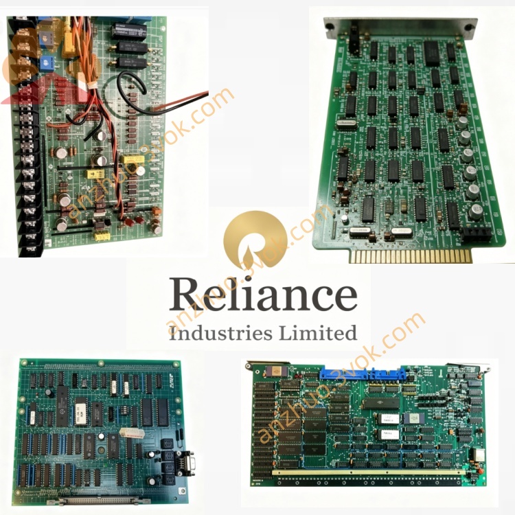
0-58704
Description
Model Definition
0-58704: Full base part number
Leading 0: Factory-original, unmodified unit
58704: Base model (Pulse Distribution/Interphase Board for MaxPak III)
-1: Common hardware revision (minor component upgrades)
Series: MaxPak III (DC Drives) / Reliance Drive Interface Boards
Variant: Standard industrial revision (no conformal coating)
Alternate P/N: 058704, 0-58704-1, 58704-1
Technical Specifications
General
Brand: RELIANCE (Reliance Electric / Baldor Reliance / ABB)
Type: Pulse Distribution / Interphase Driver Board
Form Factor: Rectangular PCB, rack-mounted (MaxPak III drive chassis)
Dimensions: ~12 in × 6 in (305 mm × 152 mm)
Weight: ~0.9 kg (2.0 lbs)
Operating Temperature: 0°C to +60°C (standard)
Storage Temperature: -40°C to +85°C
Humidity: 5%–95% non-condensing
Key Components: Pulse transformers, opto-isolators, power transistors, signal conditioning circuits
Certifications: CE, UL listed
Manual: MaxPak III Drive Technical Manual (Reliance archives)
Electrical & Control
Input Power: +15 VDC, -15 VDC, +5 VDC (from MaxPak III internal PSU)
Control Inputs: Logic-level pulse signals (from regulator board 0-58703-5)
Outputs: Isolated thyristor trigger pulses (6 channels, 3-phase)
Isolation Voltage: 2500 Vrms (control-to-power stage)
Pulse Frequency: 50/60 Hz (synchronized with line voltage)
Drive Compatibility: MaxPak III 3-phase DC regenerative drives (230V–600V DC output)
Protection: Overcurrent, short-circuit, surge suppression
Interface & Communication Configuration
Physical Interfaces
PCB Edge Connectors: Multi-pin (control signals, power, ground) for MaxPak III backplane
Pulse Output Terminals: Screw terminals for thyristor gate connections (3-phase, 6 pulses)
LED Indicators: PWR OK, PULSE ACTIVE, FAULT (onboard)
Communication
Bus Interface: Proprietary MaxPak III internal control bus
Signal Format: Digital logic pulses (input) → isolated high-energy pulses (output)
Feedback: No external communication; direct hardwired interconnection with regulator board
Core Functions
Thyristor Pulse Distribution: Generates and distributes isolated trigger pulses to 3-phase thyristor stacks for precise DC output control。
Electrical Isolation: Provides 2500 Vrms isolation between low-voltage control logic and high-power thyristor circuits, protecting sensitive components。
Signal Conditioning: Amplifies and shapes weak logic pulses to meet thyristor gate drive requirements。
Fault Monitoring: Detects pulse loss, short circuits, or power supply faults; triggers drive shutdown via backplane signals。
Regenerative Drive Support: Synchronizes pulse timing for 4-quadrant regenerative braking operation。
Application Scenarios
Legacy MaxPak III DC Drive Retrofits: Direct replacement for failed pulse distribution boards in industrial DC drive systems。
High-Power DC Motor Control: Steel mills, paper mills, cranes, hoists, and extruders using MaxPak III drives。
Regenerative Drive Systems: Applications requiring energy recovery during motor deceleration (e.g., conveyors, winders)。
3-Phase Thyristor-Based Power Conversion: Industrial rectifier systems relying on precise pulse triggering。
Usage & Maintenance Instructions
Installation
Power Off: De-energize the MaxPak III drive and connected DC motor before removal/installation.
Remove Old Board: Disconnect edge connectors and pulse output wires; release mounting screws.
Insert New Board: Align with chassis guides; seat edge connectors firmly; tighten mounting screws (torque 0.8–1.0 N·m).
Reconnect Wiring: Restore pulse output terminals to thyristor gates; verify polarity.
Operation
Power-On: PWR OK LED lights; board initializes (2–3 s); PULSE ACTIVE flashes during normal operation.
Normal Operation: PWR OK steady; PULSE ACTIVE flashes at line frequency; FAULT off.
Fault Condition: FAULT LED on; PULSE ACTIVE off; check for loose connections, shorted thyristors, or power supply issues.
Get a Quote