
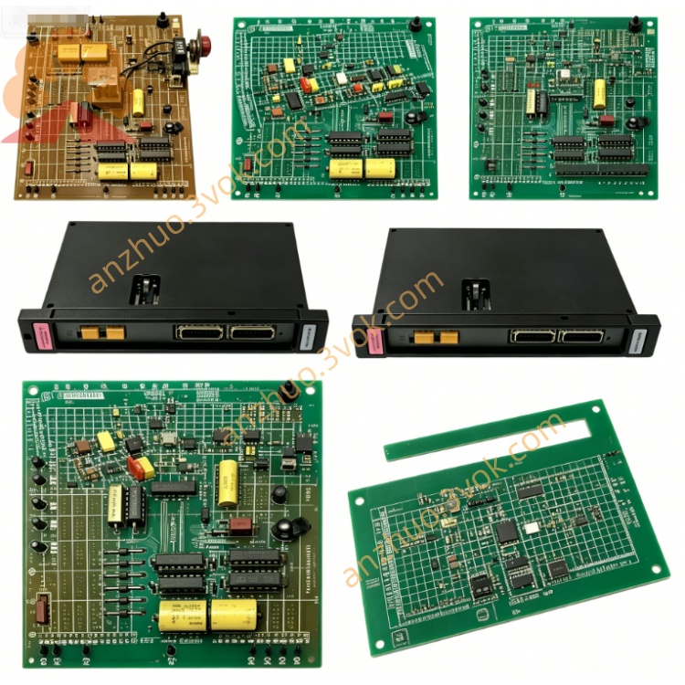
0-58703-5
Description
Model Definition
0-58703-5: Full part number
Leading 0: Factory-original, unmodified unit
58703-5: Base model (Drive Regulator Board for MaxPak III DC Drives)
Series: MaxPak III (DC Drives) / Reliance Drive Boards
Variant: Standard industrial revision (no conformal coating)
Alternate P/N: 0587035, 58703-5C
Technical Specifications
General
Brand: RELIANCE (Reliance Electric / Baldor Reliance / ABB)
Type: Drive Regulator Board (DC Drive Control Card)
Form Factor: Square PCB, rack-mounted (MaxPak III drive chassis)
Dimensions: ~12 in × 12 in (305 mm × 305 mm)
Weight: ~1.8 kg (4.0 lbs)
Operating Temperature: 0°C to +60°C (standard)
Storage Temperature: -40°C to +85°C
Humidity: 5%–95% non-condensing
Key Components: 6 transformers, 40+ integrated circuits, power regulation & feedback control circuits
Certifications: CE, UL listed
Manual: Available via Reliance/Baldor technical archives (MaxPak III Drive Manual)
Electrical & Control
Input Power: From MaxPak III drive’s internal PSU (isolated AC/DC)
Control Signals: Speed reference, current feedback, voltage feedback, enable/disable
Regulation Modes: Closed-loop speed, current, and armature voltage control
Drive Compatibility: MaxPak III three-phase DC regenerative VS drives (230V–600V DC output)
Motor Compatibility: High-power DC motors (series/separately excited)
Protection Logic: Overcurrent, overvoltage, overspeed, short-circuit, thermal overload
Interface & Communication Configuration
Physical Interfaces
PCB Edge Connectors: Multi-pin (power, control, feedback, I/O) for MaxPak III chassis backplane
Terminal Blocks: Field wiring for speed reference (0–10V/4–20mA), enable, and fault signals
Front Panel (Drive Chassis): LED indicators for POWER, RUN, FAULT, OVERCURRENT
Communication
Bus Interface: Proprietary MaxPak III drive internal bus (no external network)
Signal Format: Analog (speed reference/feedback) + digital (enable/fault logic)
Feedback Integration: Accepts armature voltage, current transformer, and tachometer encoder signals
Core Functions
Closed-Loop Speed Regulation: Maintains precise DC motor speed via tachometer/encoder feedback.
Current & Voltage Control: Regulates armature current and voltage for stable torque and power output.
Regenerative Braking Management: Controls energy recovery during deceleration (MaxPak III regenerative drives).
Fault Detection & Protection: Monitors overcurrent, overvoltage, overspeed, and thermal conditions; triggers drive shutdown on faults.
Drive System Coordination: Synchronizes with MaxPak III power stage for consistent DC output to motors.
Parameter Configuration: Onboard trim pots for speed loop gain, current limit, and voltage calibration.
Application Scenarios
Legacy MaxPak III DC Drive Retrofits: Direct replacement for failed regulator boards in industrial DC drive systems.
Heavy-Duty Motion Control: Steel mills, paper mills, cranes, hoists, and extruders using high-power DC motors.
Regenerative Drive Systems: Applications requiring energy recovery during motor deceleration (e.g., conveyors, winders).
Process Control: Industrial lines with precise speed/torque regulation (e.g., metal processing, material handling).
Usage & Maintenance Instructions
Installation
Power Off: De-energize the MaxPak III drive and connected DC motor before removal/installation.
Remove Old Board: Disconnect edge connectors and terminal wires; release mounting screws.
Insert New Board: Align with chassis guides; seat edge connectors firmly; tighten mounting screws (torque 1.0–1.2 N·m).
Reconnect Wiring: Restore terminal block connections (speed reference, enable, fault signals).
Get a Quote